NUNU is a truly appealing firmware for our beloved Quansheng K5(8)/K6 , as it incorporates a large number of very interesting options. In this tutorial, we will learn how to flash it and how to use all of its features.
The NUNU firmware is based on
EGZUMER
but with some additional modifications applied during compilation:
- ENABLE_SPECTRUM_CHANNEL_SCAN: In the spectrum analyzer, saved channels can now be scanned; it is no longer limited to a frequency range.
- NUNU Protocol: Message sending over the
MESHnetwork. - ENABLE_ENCRYPTION: Message encryption using
ChaCha20. - Fixed AM AGC: Improvements in reception quality in
AMmode. - RxOff: Allows applying an offset (0–150 MHz) when using an upconverter .
- ENABLE_SPECTRUM_COPY_VFO: Allows copying the peak frequency from the spectrum analyzer along with the adjusted parameters to
VFOmode (when exiting the analyzer). - ENABLE_SPECTRUM_SHOW_CHANNEL_NAME: The channel
IDand name are shown in the spectrum analyzer. - ENABLE_ADJUSTABLE_RX_GAIN_SETTINGS: Allows copying the adjusted gain parameters from the spectrum analyzer to
VFOmode (when exiting the analyzer). These will be preserved until the walkie is rebooted or switched toAMmode. - VOXSen: Improved
VOXsensitivity. - VoxDel: Silence delay before the
VOXstops listening, useful forAPRS. - SqTone: Configurable tail tone when using
CTCSStones.
However, several features have also been removed or reduced due to the limited capacity of the walkie:
FM broadcastradio: Micro Size- UNBLOCK ALL: It does not allow unlocking any frequency, since outside amateur radio bands the resulting transmit power would be very poor.
DTMF: There are noDTMFcalls; it only allows sendingDTMFtones and decoding them on screen.
If you are new to the world of amateur radio, I recommend this previous article , which explains the fundamentals.
The article is composed of the following sections:
- Reflashing
- Spectrum analyzer
- Scan frequency range function
- Battery calibration
- Functions
- Buttons and functions
- Unlock frequencies
- Frequency scanner
- Scrambling
- Remote kill
- CHIRP
- Messenger
- MESH Network
Reflashing:
Before starting, we must install
Mono
in Wine-Linux and then make a backup of the configuration and calibration files as indicated in
this previous article
.
It is also recommended to save the current radio configuration, as this will be useful later to load the channels into the new firmware. We save it twice: in CHIRP format and in CSV format, since if there are issues loading it, the CSV file can be edited by modifying or removing conflicting fields.
To perform the backup, we just need to follow these steps in CHIRP :
Radio -> Download from radioFile -> Save As ...File -> Export to CSV ...
Now we can proceed with reflashing by following the steps indicated in this previous article , obviously selecting the firmware file corresponding to NUNU .
Spectrum analyzer:
The
NUNU spectrum analyzer
is very similar to that of
EGZUMER
, but NUNU allows three operating modes. If we access it from VFO mode, it will enter frequency scanner mode; if accessed from MR mode, it will enter channel scanner mode; and if accessed from ScnRng mode, it will enter ScnRng mode.
Frequency scanner mode: 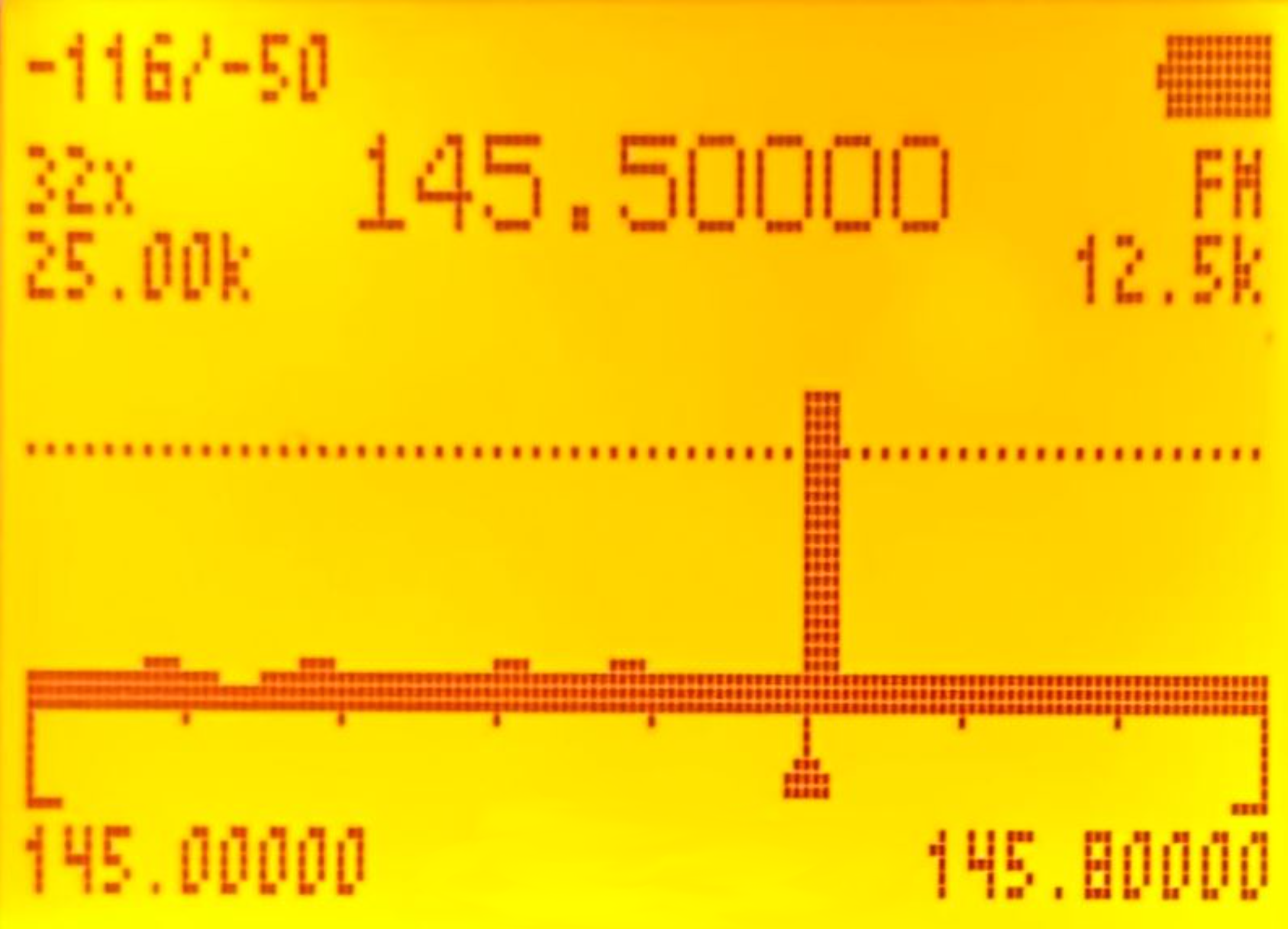
To make it easier to understand, I will show the data in a table where each row represents a line of information on the display. Each parameter is also accompanied by an image from the example above:
| First display column | Display | Second display column | Display | Third display column | Display |
|---|---|---|---|---|---|
| Y-axis zoom: Maximum/current value. 3(VFO/MR)/9(Call) |
 |
Battery | |||
| Number of channels to scan: How many channels (within the indicated bandwidth) should be monitored starting from the initial frequency. 4(FC) |
Frequency at which the strongest signal has been detected within that frequency range. |  |
Modulation type. 0(FM) |
||
| Bandwidth of each channel. 1(Band)/7(VOX) |
 |
Bandwidth used to analyze each channel; depending on the signal emission, one bandwidth may be better than another. 6(H/M/L) |
 |
||
| Squelch line. *(Scan)/F(#) |
 |
Squelch line. | |
Squelch line. | |
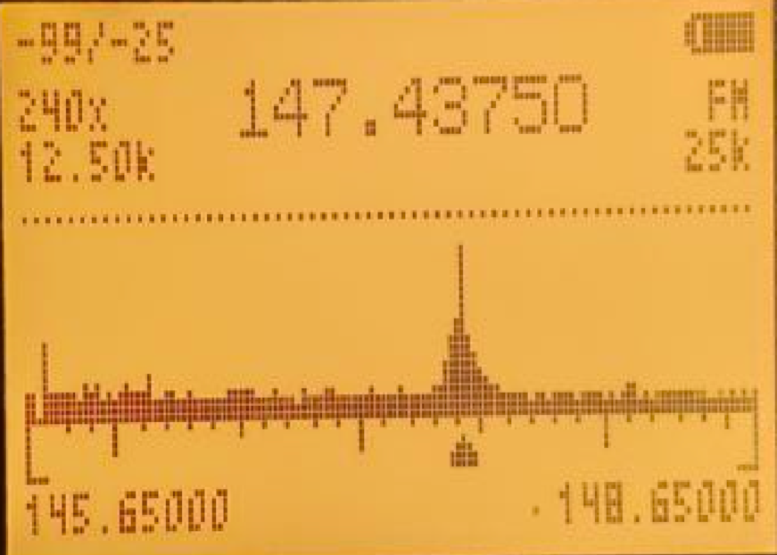
| Spectrum: The small triangle at the bottom shows the frequency with the highest intensity, also shown numerically at the top. | 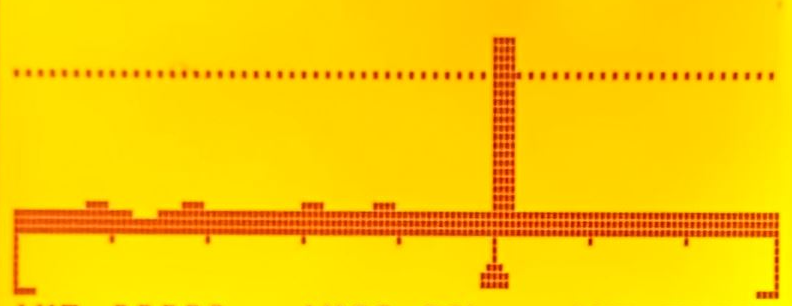 |
Spectrum. | |
Spectrum. | |
| Initial frequency. 5(NOAA) |
 |
Final frequency. |  |
If we press 5(NOAA) in this mode, we can manually enter the frequency. We must press * to enter . and finally M(A) to confirm.
NOTE: If the squelch is exceeded, it only shows the real-time state of that frequency (145.500 in the screenshot); the rest stop being monitored in real time.
- In the example, we can see that it is monitoring 32 channels of 25 kHz: 32 × 25 = 800 kHz.
- The initial frequency is 145.00000, therefore the final frequency is 145.00000 + 800 = 145.80000 kHz.
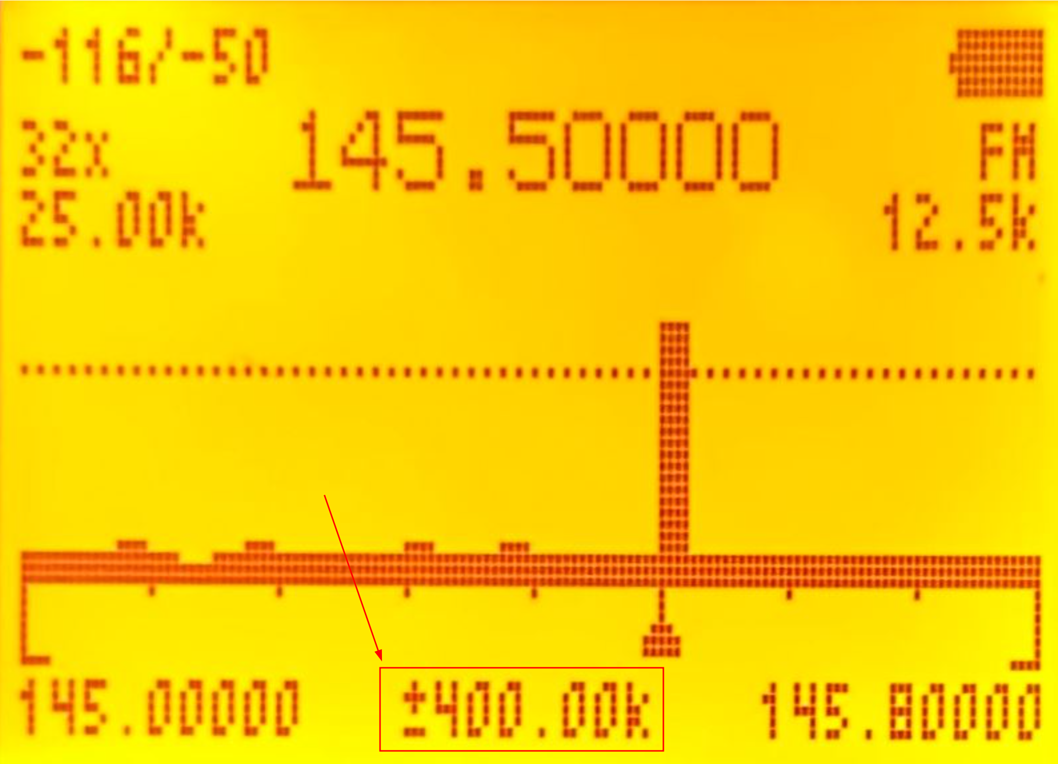
- If we press the Up (B) / Down (C) arrows, we move through the spectrum by
(N channels × BW) / 2kHz → 32 channels of 25 kHz: (32 × 25 = 800 kHz) / 2 = 400 kHz. That is, if we press the Up arrow (B), the initial frequency will be 145.40000 and the final frequency 145.40000 + 800 = 146.20000 kHz. - The Y-axis zoom is set to -50 and the channels are being analyzed using 12.5 kHz.
We must take into account that in the official documentation a screenshot is shown that does not actually correspond to what is displayed by the firmware. It must be an old screenshot in which the spectrum analyzer displacement was shown when pressing the arrows:
| Showing displacement (old version) | Not showing it (current version) |
|---|---|
|

|
Channel scanner mode: 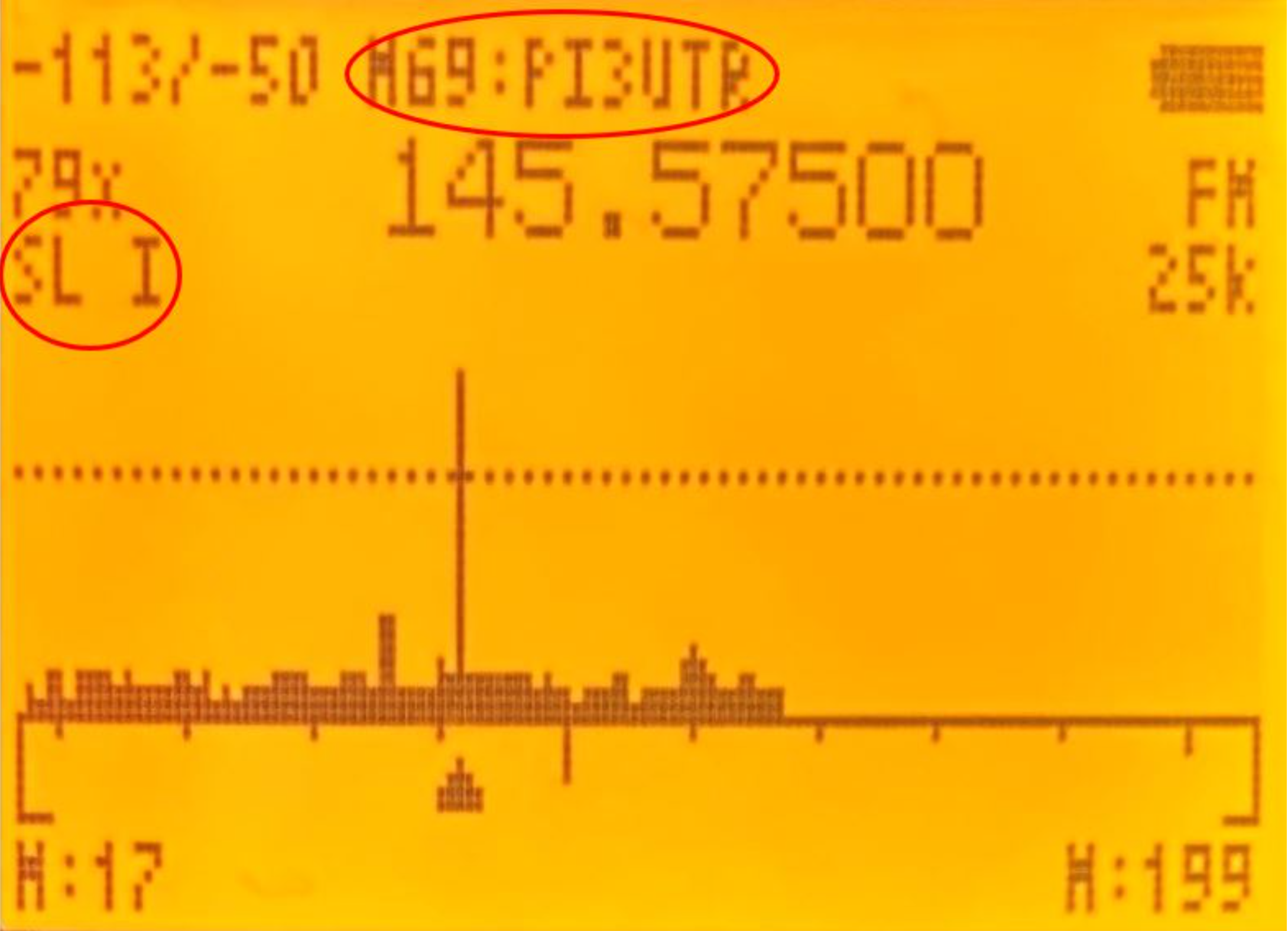
To make it easier to understand, I will again show the data in a table where each row represents a line of information on the display:
| First display column | Display | Second display column | Display | Third display column | Display |
|---|---|---|---|---|---|
| Y-axis zoom: Maximum/current value. 3(VFO/MR)/9(Call) |
 |
Channel ID and name where the strongest signal has been detected. |  |
Battery | |
| Number of channels being scanned: This depends on the ScanList we are using (shown on the bottom line). | Frequency at which the strongest signal has been detected within that group of channels. |  |
Modulation type. 0(FM) |
||
| ScanList used to scan channels. 4(FC) |
 |
Bandwidth used to analyze each channel; depending on the signal emission, one bandwidth may be better than another. 6(H/M/L) |
 |
||
| Squelch line. *(Scan)/F(#) |
 |
Squelch line. | |
Squelch line. | |
| Spectrum: The small triangle at the bottom shows the strongest frequency, also shown by channel ID, channel name, and numerically at the top. | 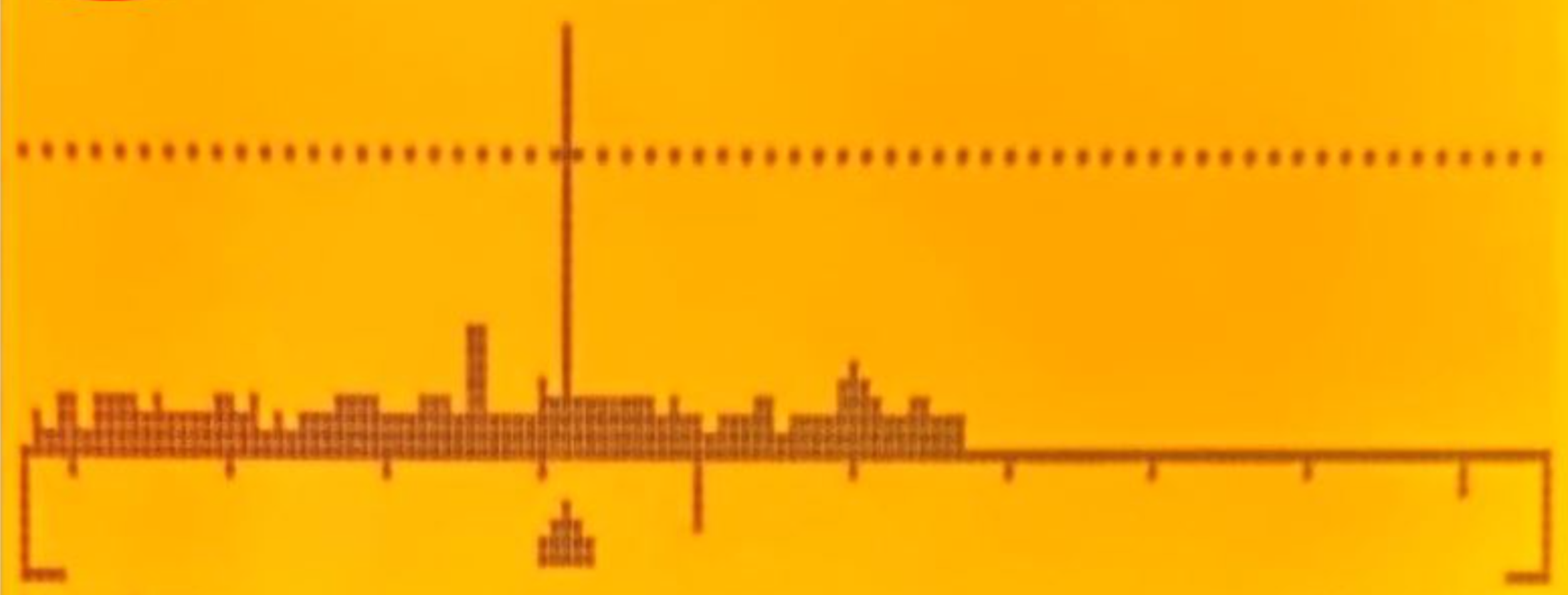 |
Spectrum. | |
Spectrum. | |
| Initial channel. This depends on the active ScanList. |  |
Final channel. This depends on the active ScanList. |  |
In this mode, if it detects any channel that exceeds the squelch, it will not draw the entire spectrum, but only up to slightly beyond the first channel that exceeds the squelch. I am not sure whether this is a bug or an issue:
| Squelch exceeded | Squelch not exceeded |
|---|---|
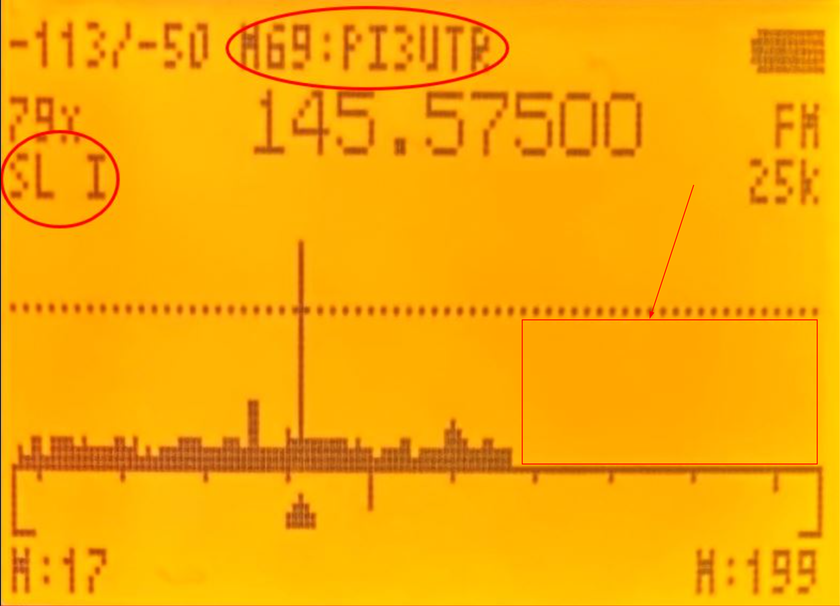
|
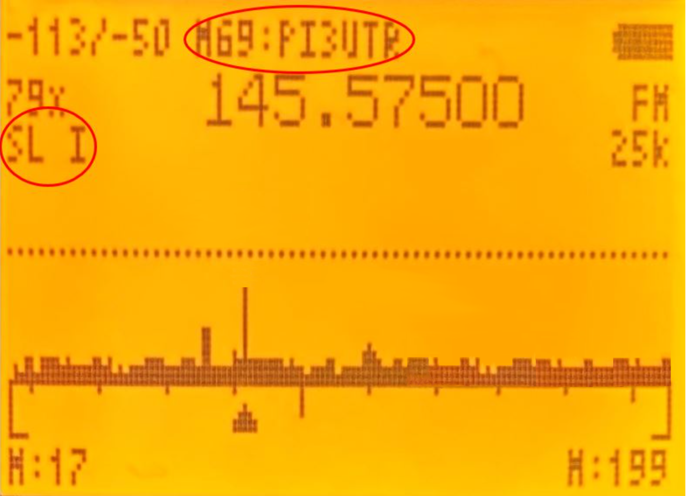
|
ScnRng mode:
The ScnRng mode allows us to define the frequency range to be scanned in the spectrum analyzer. We only need to access
ScnRng mode
(hold down 5) and then press F+5.
This mode operates exactly the same as Frequency scanner mode, but if the frequency range to be scanned is excessively large, the analyzer will become very slow. For example, if we modify the squelch, it will be applied immediately, but channels that exceed that squelch will only be detected when the frequency sweep reaches that point (which may take a while).
In this mode we have the same issue as in Channel scanner mode: when the squelch is exceeded, part of the graph is missing.
| Squelch exceeded | Squelch not exceeded |
|---|---|
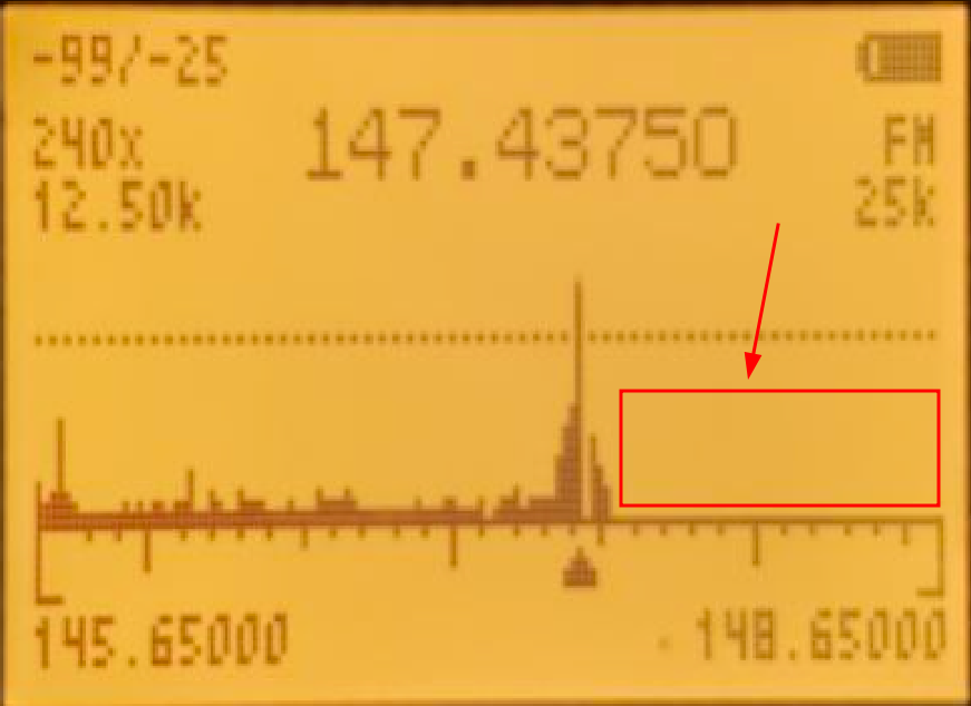
|
|
Detailed monitoring: 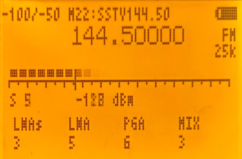
To access detailed monitoring, we must press M(A). In the example, we can see a level 5 signal equivalent to -128 dBm, which barely exceeds the Squelch level.
In this menu we can also make some adjustments:
| Button | Function |
|---|---|
| Up arrow (B) | Increases the current frequency. |
| Down arrow (C) | Decreases the current frequency. |
| 3(VFO/MR)/9(Call) | Y-axis zoom: Maximum/current value. Although in this view it is not useful. |
| 5(NOAA) | Allows manual frequency entry; press * to enter . and finally M(A) to confirm. |
| 6(H/M/L) | Bandwidth used to analyze each channel; depending on the signal emission, one bandwidth may be better than another. |
| *(Scan)/F(#) | Squelch adjustment. |
| 0(FM) | Changes the modulation type. |
| SideKey1 | Opens the squelch. |
| SideKey2 | Enables/Disables the backlight. |
| Exit (D) | Return to the normal spectrum analyzer view. |
To access the different parameters shown below, we must press M(A) and move using the Up (B) / Down (C) arrows:
| Parameter | Function |
|---|---|
| LNAs | Low Noise Amplifier (Short): Amplifies the signal while introducing as little noise as possible; explanation of values below (LNA: Low Noise Amplifier). |
| LNA | Low Noise Amplifier: Amplifies the signal while introducing as little noise as possible; explanation of values below. |
| PGA | Programmable Gain Amplifier: Amplifies the signal after being amplified by the LNA, mixed by the MIXER, and filtered; explanation of values below (IF: Image rejection architecture). |
| MIX | Quadrature mixer: Directly converts the RF signal into an IF signal. |
NOTE: Unlike
EGZUMER
, NUNU allows modifying the MIXER value but not the IF filter (filter inside the Filter+VGA+ADC block shown below), while EGZUMER allowed modifying the IF but not the MIXER.
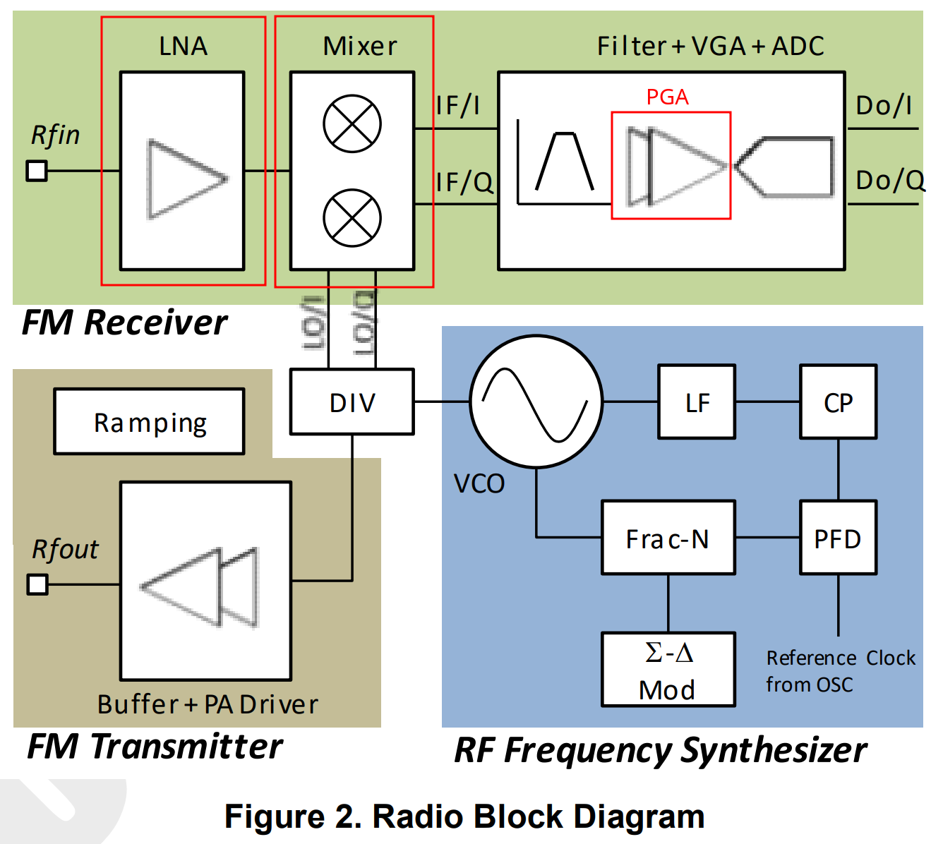
Below is the general diagram of incoming signal processing and each of the elements that NUNU allows adjusting (LNA/MIXER/PGA).
Input signal diagram:
From the radio chip datasheet
BK4819.pdf
, we can see that the signal enters through the antenna, passes through the LNA where it is amplified, then through the MIXER, enters the IF, passes through a filter, is amplified again using the VGA (PGA), and is finally digitized.
Keep in mind that the datasheet refers to IF as the combination Filter + VGA (PGA) + ADC, while in the NUNU firmware (VGA = PGA).
In the diagram, I have marked in red how NUNU and EGZUMER name each part:
| NUNU | EGZUMER |
|---|---|
|
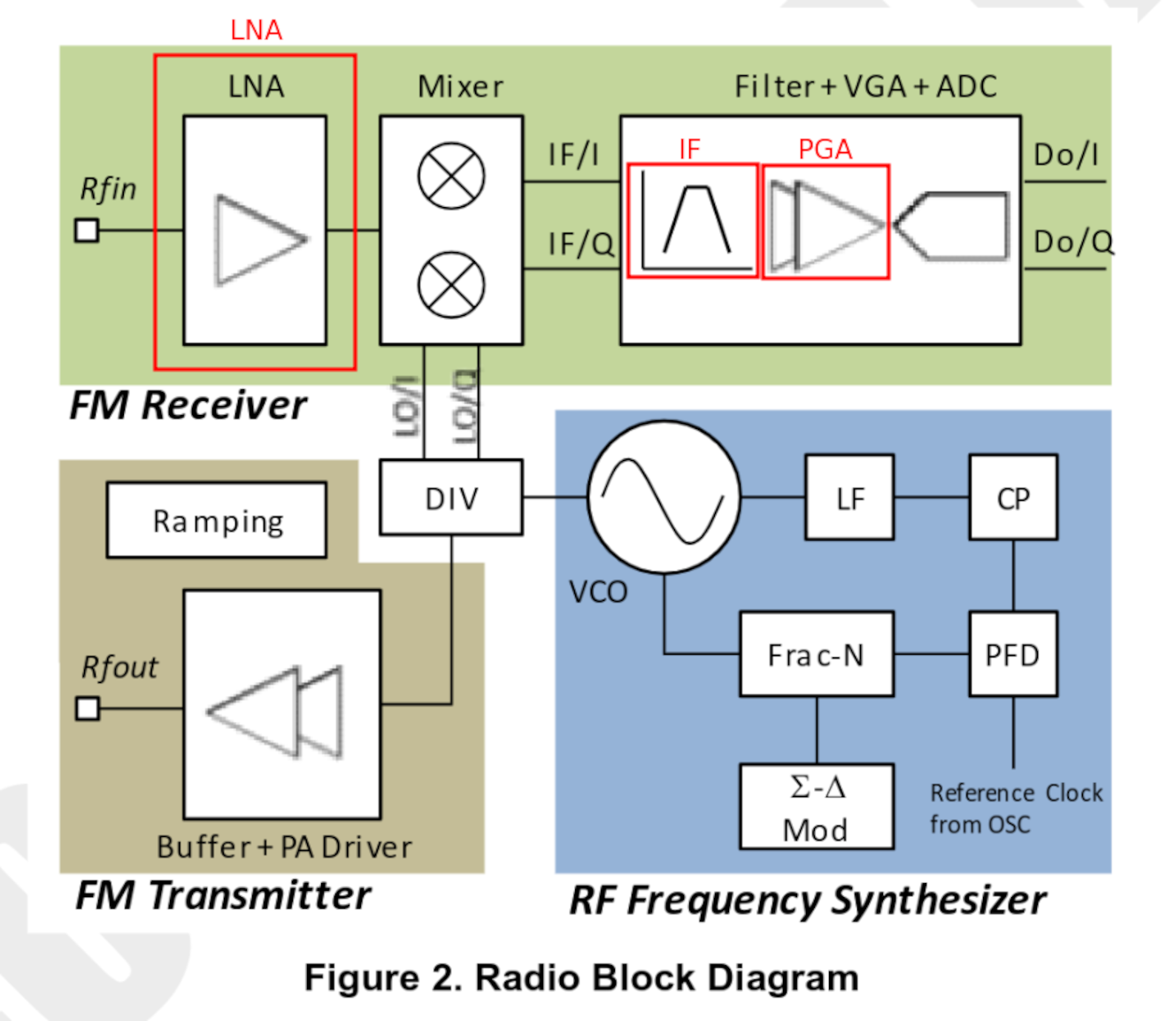
|
LNA: Low Noise Amplifier
Weak signals must be amplified while introducing as little noise as possible. We must keep in mind that when amplifying a signal, we amplify the signal itself, the noise already present in the received signal, and the noise introduced by the amplification circuitry. 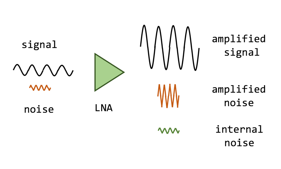
The amplification is controlled by the RF module register: REG_10<9:8>/<7:5>
BK4819V3Registers_List
- LNA Gain Short is a 2-bit field, so we have 4 possible values:
| Binary value | Decimal value | Gain |
|---|---|---|
| 00 | 0 | -19 dB |
| 01 | 1 | -16 dB |
| 10 | 2 | -11 dB |
| 11 | 3 | 0 dB |
- LNA Gain is a 3-bit field, so we have 8 possible values:
| Binary value | Decimal value | Gain |
|---|---|---|
| 000 | 0 | -24 dB |
| 001 | 1 | -19 dB |
| 010 | 2 | -14 dB |
| 011 | 3 | -9 dB |
| 100 | 4 | -6 dB |
| 101 | 5 | -4 dB |
| 110 | 6 | -2 dB |
| 111 | 7 | 0 dB |
The total gain is the sum of LNA Gain Short + LNA Gain. For example, if we configure:
- LNA Gain Short: 0 → 00 → -19 dB
- LNA Gain: 2 → 010 → -14 dB
The final gain will be: -19 − 14 = -33 dB
MIXER: Quadrature mixer
The MIXER is controlled by the RF module register: REG_10<4:3>
BK4819V3Registers_List
MIXER Gainis a 2-bit value, so we have 4 possible values:
| Binary value | Gain |
|---|---|
| 00 | -8 dB |
| 01 | -6 dB |
| 10 | -3 dB |
| 11 | 0 dB |
PGA: Programmable Gain Amplifier
This is a programmable signal amplifier, meaning it can be configured with different values. The gain is controlled by the RF module register: REG_10<2:0>
BK4819V3Registers_List
- PGA is a 3-bit value, so we have 8 possible values:
| Binary value | Decimal value | Gain |
|---|---|---|
| 000 | 0 | -33 dB |
| 001 | 1 | -27 dB |
| 010 | 2 | -21 dB |
| 011 | 3 | -15 dB |
| 100 | 4 | -9 dB |
| 101 | 5 | -6 dB |
| 110 | 6 | -3 dB |
| 111 | 7 | 0 dB |
Additional functions:
In addition to the functions shown above in each operating mode, there are some common to all three modes:
| Button | Function |
|---|---|
SideKey1 |
Excludes the current freq/channel from scanning, moving on to the next strongest signal. In Spectrum analyzer mode, the maximum number of blacklisted frequencies is 200. A BL will be shown at the bottom of the screen: |
SideKey2 |
Freq/channel attenuation. Useful when a signal is very strong and interferes with scanning, forcing you to blacklist the channel or raise the squelch. It only works when the active ScanList has ≤ 128 channels or when the number of channels analyzed in Frequency scanner mode does not exceed 128 channels. The same freq/channel can be attenuated multiple times. A ATT will be shown at the bottom of the screen: |
F+2(A/B) / P.prolong 2(A/B) |
Applies normalization to the spectrum bars, allowing the display to auto-adjust and improve visualization. It only works when the active ScanList has ≤ 128 channels or when the number of channels analyzed in Frequency scanner mode does not exceed 128 channels. An N(XX) will be shown in the channel count:  |
M(A) |
Switches to detailed monitoring. |
Up(B)/Down(C) |
Resets the blacklist and normalization. In Frequency scanner mode, it also advances by (N channels × BW) / 2 kHz. |
PTT |
Exits the spectrum analyzer or the Detailed monitoring window while copying the parameters to VFO/MR mode. |
If we enter the spectrum analyzer from VFO/MR mode, all parameters are also copied. |
NOTE: If the spectrum analyzer freezes or AM reception is heavily distorted, we can disconnect the antenna and lower the LNA parameters.
Scan frequency range function:
This firmware allows us to scan a frequency range without having to switch bands. We only need to use the first row of the display to indicate the start frequency and the second row to indicate the end frequency. Hold down 5(NOAA) to access this function and hold down *(Scan) to start scanning.
If we press EXIT(D), the scan stops and returns to the initial frequency. If we press PTT/M(A), it will remain on the last frequency where a signal was detected. Up(B)/Down(C) change the scan direction.
If we have entered Scan frequency range mode but want to exit, we can do so in two different ways: by holding down 5(NOAA) or by holding down Exit(D).
It is also possible to enter a stored channel on one row and a frequency on the other row, scanning between the two. Additionally, remember that we can use Scan frequency range from the
spectrum analyzer
.
Battery calibration
To perform the configuration, we must access the extended menu:
SideKey1 + PTT + Power On
| Option | Menu ID | Function |
|---|---|---|
| BatCal | 60 | Allows defining the current battery voltage to readjust the value shown on screen. |
| BatTyp | 61 | There are two battery types; depending on the model, the discharge curve varies. Knowing the battery type allows the percentage to be calculated more accurately. |
| 1600mAh: 1600mAh version. | ||
| 2200mAh: 2200mAh version. |
Calibration can be done in two different ways:
| Manually: Fully charge the battery to 100% and adjust the BatCal (60) value until the display shows 100%. | Multimeter: Use a multimeter to check the real voltage. |
|---|---|
As we can see, when returning to the main menu the value changes. This appears to be a firmware bug; re-entering the option and reapplying the value causes it to be displayed correctly outside the menu as well.
Functions
To access the options, press the M(A) button and navigate using the arrow keys. We can also access options quickly if we know their ID. For example, if we know that the VOX option is 43, we can press M(A) + 43.
The following table lists all the functions supported by NUNU. Items marked in bold indicate functionality added compared to the
stock firmware
, and items underlined indicate functionality added compared to
EGZUMER
.
| Option | Menu ID | Function |
|---|---|---|
| Step | 1 | How many kHz the frequency will advance or decrease when scanning or manually changing frequency. |
| Bandw | 2 | Bandwidth to use. Normally Wide: 25kHz / Narrow: 12.5kHz, but NUNU allows finer tuning. Keep in mind: |
| Larger bandwidth: shorter range, better audio quality. | ||
| Smaller bandwidth: longer range, worse audio quality. | ||
| 5 / 6.25 / 8.33 / 12.5 / 25 kHz | ||
| TxPwr | 3 | Transmit power. High power may affect adjacent channels: |
| LOW: 1W | ||
| MID: 3W | ||
| HIGH: 5W | ||
| RxDCS | 4 | Digital receive code : If we are on a frequency but don’t know the transmit code being used by the other party, we can press F+*(Scan) and the radio will start scanning DCS codes until it automatically finds the correct one. |
| RxCTCS | 5 | Analog receive sub-tone : If we don’t know the transmit tone being used, press F+*(Scan) and the radio will scan CTCS tones until it finds the correct one. |
| TxDCS | 6 | Digital transmit code . |
| TxCTCS | 7 | Analog transmit sub-tone . |
| TxODir | 8 | Applies a positive (+) or negative (–) offset, used for repeaters . |
| TxOffs | 9 | Offset applied during transmission when using repeaters . |
| RxOffs | 10 | There are
devices
that can be connected to the radio antenna to receive frequencies the radio cannot normally receive. These devices shift the incoming signal to a frequency the radio can receive. This option applies a positive offset so the display shows the actual receive frequency, simulating direct reception. Transmission on that frequency is disabled, as upconverters are receive-only. For example, if the radio can receive at 100 MHz and the upconverter works at 300 MHz, we configure the radio in VFO mode to 100 MHz and set RxOffs to 200 MHz (100 + 200 = 300).This can also be used as RIT, explained in the
IJV article
. |
| Scramb | 11 | Encrypted communication : Allows 1–10 scrambling types. |
| BusyCL | 12 | Busy Channel Lock: Prevents transmission if the channel is busy. |
| Compnd | 13 | Compander (Compressor/Expander). Allows signals with wide dynamic range (like a microphone) to be transmitted over a narrower channel. This improves audio quality by reducing noise and crosstalk . Must be enabled on both radios: |
| TX: Enables compander only for transmission. | ||
| RX: Enables compander only for reception. | ||
| TX/RX: Enables compander for both transmission and reception. | ||
| OFF: Disables compander. | ||
| Demodu | 14 | Changes the modulation type : |
| FM: Default. | ||
| AM: Receive only. | ||
| USB: Receive only. | ||
| RxAGC | 15 | Receive Automatic Gain Control: Automatically adjusts receive gain so signals arrive at a stable level, preventing them from being too loud or too weak. Works with all modulation types. |
| OFF: Disabled, maximum gain, useful for weak signals. | ||
| SLOW: Gain applied slowly; works well in most cases, especially for HF-AM broadcast stations. | ||
| FAST: Gain applied quickly; suitable for short voice communications such as aviation. | ||
| ScAdd1 | 16 | In
channel mode
, allows adding the channel to ScanList1 directly from the radio. |
| ScAdd2 | 17 | In
channel mode
, allows adding the channel to ScanList2 directly from the radio. |
| ChSave | 18 | Save channel. |
| ChDele | 19 | Delete channel. |
| ChName | 20 | Allows editing the channel name directly from the radio. |
| ScnRev | 21 | Scan options: |
| CARRIER: When a signal is detected, scanning pauses as long as the signal is active. | ||
| STOP: When a signal is detected, scanning stops for 5 seconds and then continues. | ||
| TIMEOUT: Stops scanning when a signal is detected. | ||
| F1Shrt | 22 | Configuration of the SKey1 button directly from the radio: |
| FLASH LIGHT: Turns on the flashlight. | ||
| POWER: Changes transmit power. | ||
| MONITOR: Opens squelch (53). | ||
| SCAN: Starts scanning. | ||
| VOX: Enables VOXSen (43). | ||
| FM RADIO: Accesses the FM radio. | ||
| LOCK KEYPAD: Locks the keypad. | ||
| SWITCH VFO: Switches between channel A and B. | ||
| VFO/MR: Switches operating mode . | ||
| SWITCH DEMODUL: Changes modulation type. | ||
| SWITCH BANDWID: Changes bandwidth. | ||
| SPECTRUM: Accesses the spectrum analyzer . | ||
| NONE: Disables the button. | ||
| F1Long | 23 | Same as F1Shrt, but for a long press. |
| F2Shrt | 24 | Configuration of the SKey2 button. |
| F2Long | 25 | Same as F2Shrt, but for a long press. |
| MLong | 26 | Same as F1Shrt, but for a long press of M(A). |
| KeyLck | 27 | Automatic keypad lock. |
| TxTOut | 28 | Maximum transmit time limit. Even if PTT is held, transmission will stop after X seconds. Useful to save battery, prevent overheating, or avoid accidental transmission in a backpack. |
| BatSav | 29 | Active/inactive time ratio to save battery. If too aggressive, incoming signals may be missed. When enabled, PS appears in the upper-left corner of the display. |
Options: Off / 50% / 67% / 75% / 80% |
||
| Mic | 30 | Microphone sensitivity. |
| ChDisp | 31 | How a stored channel is displayed on screen: |
| NAME: Shows channel name. | ||
| NAME + FREQ: Shows channel name and frequency. | ||
| FREQ: Shows frequency only. | ||
| CHANNEL NUMBER: Shows channel number. | ||
| POnMsg | 32 | Power-on message: |
| FULL: Shows a fully black screen, useful to detect dead pixels. | ||
| MESSAGE: Message configured via CHIRP . | ||
| VOLTAGE: Battery voltage and charge. | ||
| NONE: Shows nothing; directly displays the A/B channel screen. | ||
| BatTxt | 33 | How battery charge is displayed: |
| NONE: Only shows the battery bars. | ||
| VOLTAGE: Shows voltage next to the battery. | ||
| PERCENT: Shows percentage next to the battery. | ||
| BatLt | 34 | Screen backlight behavior: |
| OFF: Always keeps backlight at BLMin (35). | ||
| ON: Always keeps backlight at BLMax (36). | ||
| 5/10/20s 1/2/4m: Uses BLMax while active and BLMin after X inactivity time. | ||
| BLMin | 35 | Minimum screen brightness. |
| BLMax | 36 | Maximum screen brightness. |
| BltTRX | 37 | Enables backlight on transmit and/or receive: |
| OFF / TX / RX / TX/RX | ||
| Beep | 38 | Enables/disables the keypress beep. |
| Roger | 39 | Sends a sound when releasing PTT to indicate end of transmission: |
| OFF / ROGER (beep) / MDC (frog-like sound) | ||
| SqTone | 40 | Squelch Tail Elimination. Adds an inaudible tone at the end of transmission to prevent squelch noise when releasing PTT. In NUNU, this tone is configurable. |
| 1 Call | 41 | Assigns the channel used when pressing 9(Call) , similar to old mobile phone speed dial. |
| D Live | 42 | Displays received DTMF codes on screen. |
| VOXSen | 43 | Audio level threshold at which VOX starts transmitting. |
| VOXDel | 44 | Silence delay before VOX stops transmitting, in 128 ms increments. 0 means no delay (useful for APRS). For voice, a minimum delay is recommended to avoid cutting off speech. |
| BatVol | 45 | Displays battery voltage and remaining charge percentage. |
| RxMode | 46 | Channel receive mode: |
| MAIN ONLY: Only listens and transmits on the main channel. | ||
DUAL RX RESPOND: Listens on both channels simultaneously. If a signal is received on the secondary channel, you can reply on that channel for the next 4 seconds. The secondary channel will be marked with the > symbol, and >< will appear at the top of the screen during those 4 seconds. |
||
| CROSS BAND: Listens on the secondary channel and transmits on the primary channel. | ||
| MAIN TX DUAL RX: Listens on both channels simultaneously, but always transmits on the primary channel. | ||
| Passwd | 47 | Requests a 4-digit PIN at startup. Also prevents reading radio data via the Kenwood-K1 cable, protecting message encryption passwords. After 3 incorrect attempts, the radio performs a factory reset. To disable, press Up(B)/Down(C) instead of entering a PIN. |
| EncKey | 48 | Displays the hash of the message encryption key. Useful to verify that two radios can communicate. Press M(A) to change the key. |
| MsgEnc | 49 | Enables/disables text message encryption. |
| MsgRx | 50 | Enables message reception. If disabled, messages can be sent but not received. |
| MsgAck | 51 | If enabled, sends an ACK for each received message, allowing the sender to know the message was delivered. Any NUNU radio can reply, but the specific receiver is not identified. |
| MsgMod | 52 | Modulation used for messaging, depending on conditions: |
| FSK 450 – bad conditions | ||
| FSK 700 – medium conditions | ||
| AFSK 1.2K – good conditions | ||
| Sql | 53 | Signal detection threshold. 0 means open squelch (all noise). Low values increase battery consumption since the radio is always listening. |
If we enter the extended menu, we can see additional configuration parameters. To do so, power on while pressing:
SideKey1 + PTT + Power On
| Option | Menu ID | Function |
|---|---|---|
| F Lock | 54 | Assigns allowed bands for transmission and reception. |
| Tx 200 | 55 | Enables transmission on 200 MHz F4. |
| Tx 350 | 56 | Enables transmission on 350 MHz F5. |
| Tx 500 | 57 | Enables transmission on 500 MHz F7. |
| 350 En | 58 | Enables reception on 350 MHz F5. |
| ScraEN | 59 | Enables the scrambling option Scramb (11). If disabled here, the option will appear in the normal menu but will not apply distortion. |
| BatCal | 60 | Sets the current battery voltage to recalibrate the displayed value. |
| BatTyp | 61 | There are two battery types ; knowing the correct type allows more accurate percentage calculation. |
| 1600mAh: 1600 mAh version. | ||
| 2200mAh: 2200 mAh version. | ||
| Reset | 62 | Reset options: |
| VFO: Resets configuration parameters. | ||
| ALL: Resets configuration parameters and stored channels. |
Buttons and functions
| Button | Function |
|---|---|
Knob |
Power on/off and volume control. |
M(A) |
Main configuration menu. Configurable from
PC
or directly on the radio: long press MLong(26). |
Up(B)/Down(C) |
Allows navigating through the menu and changing parameters. |
Exit(D) |
Exit the menu. |
PTT |
Push To Talk. If keys are pressed while transmitting, their DTMF codes will be sent. |
SideKey1 |
Configurable from
PC
or the radio: short press F1Shrt(22) / long press F1Long(23). |
SideKey2 |
Configurable from
PC
or the radio: short press F2Shrt(24) / long press F2Long(25). |
PTT+SideKey2 |
Emits a 1750 Hz tone, required to access some repeaters . |
SP/MIC connector |
Speaker/microphone (Kenwood-K1) and PC connector. |
USB-C |
USB-C charging port, use only in case of emergency. |
*(Scan) |
Allows sending DTMF codes (remember that in NUNU
DTMF calls have been removed
); SideKey1 deletes entries. |
0(FM) |
Enters the frequency in VFO mode or the channel number in channel mode . |
F(#) |
Activates function mode. |
All keypad buttons have a special function that can be activated either by pressing F(#) + Key or by holding the key marked with that function for a few seconds:
| Function | Description |
|---|---|
F+0(FM) / Long press 0(FM) |
Activates the FM broadcast radio. As stated in the official documentation , the broadcast radio section has been completely rewritten, implementing a very reduced version with no ability to store channels. |
Up(B)/Down(C): Navigate between commercial FM radio stations. |
|
F+1(Band) / Long press 1(Band), VFO mode |
Switches between available bands. |
F+1(Band) / Long press 1(Band), MR mode |
Copies the channel frequency and parameters into VFO mode. |
F+2(A/B) / Long press 2(A/B) |
Switches between the two display lines. |
F+3(VFO/MR) / Long press 3(VFO/MR) |
Switches between VFO mode and memory channels . |
F+4(FC) / Long press 4(FC) |
Enters
frequency and code/sub-tone detection mode
. Press *(Scan) if an incorrect value was detected. |
F+5(NOAA) |
Accesses the spectrum analyzer . |
Long press 5(NOAA), VFO mode |
Scans a frequency range . |
Long press 5(NOAA), MR mode |
Toggles the channel between scan lists. |
F+6(H/M/L) / Long press 6(H/M/L) |
Changes transmit power TxPwr(3). |
F+7(VOX) / Long press 7(VOX) |
Activates VOX (43). |
F+8(R) / Long press 8(R) |
Activates reverse mode . |
F+9(Call) / Long press 9(Call) |
Switches to the channel configured in menu option 1 CALL(41). |
F+*(Scan) |
Detects the code/sub-tone on a frequency or channel. |
Short press *(Scan) |
Allows entering DTMFs. Press SideKey1 to delete. |
Long press *(Scan), VFO mode |
Starts scanning from the current frequency. Press EXIT(D) to stop and return to the original frequency; press PTT/M(A) to stay on the last frequency where a signal was detected. Up(B)/Down(C) change scan direction. |
Long press *(Scan), MR mode |
Starts scanning the enabled scan lists. Pressing Long press *(Scan) again switches the ScanList. EXIT(D) stops scanning and returns to the original channel; PTT/M(A) stays on the last channel where a signal was detected. Up(B)/Down(C) change scan direction. |
Long press F(#) |
Locks the keypad. |
F+M(A) |
Accesses the messenger . |
Unlocking frequencies
NUNU does not allow unlocking any frequency, since outside amateur radio bands the resulting transmit power would be extremely poor.
Additionally, the radio could be damaged if this were allowed, so NUNU protects the user:
This (Hidden-menu) option is completely removed, to make radio more safe by default
What is allowed is some configuration within the bands supported by the radio:
FM:            F1 50∽76 MHz
FM:            F2 108∽135.9975 MHz
FM:            F3 136∽173.9975 MHz
FM:            F4 174∽349.9975 MHz
FM:            F5 350∽399.9975 MHz
FM:            F6 400∽469.9975 MHz
FM:            F7 470∽599.9975 MHz
FM:            F7+ XXXXX-XXXXX MHz
AM:            F2 108∽135.9975 MHz
To configure this, we must access the extended menu, from which we can reach the different options :
SideKey1 + PTT + Power On
Important considerations:
- By default, reception is enabled on all bands; the only exception is
F5, controlled by the350 Enoption. - The remaining options control transmission on the different bands.
F Lockenables common frequency ranges depending on geographic region.- The special
DEFAULToption ofF Lockenables additional ranges beyond 137–174 and 400–470 usingTx 200,Tx 350, andTx 500. Tx XXXenables additional bands only ifDEFAULTis selected.
F Lock(54) – Assigns allowed transmit bands.
    DEFAULT + (137-174, 400-470) – Enables transmission on F3 and F6, expandable via Tx 200, Tx 350, Tx 500.
    FCC HAM (144-148, 420-450)
    CE HAM (144-146, 430-440)
    GB HAM (144-148, 430-440)
    (137-174, 400-430)
    (137-174, 400-438)
    DISABLE ALL – Disables transmission on all frequencies.

Tx 200 – Enables transmission on 200 MHz F4.
Tx 350 – Enables transmission on 350 MHz F5.
Tx 500 – Enables transmission on 500 MHz F7.

350 En – Enables reception on 350 MHz F5.
In my case, I will enable only the typical amateur radio frequencies. The corresponding configuration options are:
F Lock(54): DEFAULT + (137-174, 400-470)
Tx 200 – OFF
Tx 350 – OFF
Tx 500 – OFF
350 En – ON
As shown, with this configuration we can receive on all bands but transmit only on amateur radio bands:
Keep in mind that even after unlocking frequencies, transmission will always be FM; transmitting in AM or USB is not possible.
Frequency scanner
This firmware has a very interesting function called Frequency Copy (FC), which allows us to determine the frequency and the
tone/code
being used by another radio. We just need to activate this function: F+4 (FC) / P.prolong 4 (FC) and wait for the other radio to transmit. We can press * (Scan) if an incorrect frequency was detected.
This is very useful when working with people who are inexperienced in the radio hobby and do not know what parameters they have configured.
Another functionality related to FC is the Tone/Code scanner. If we know the frequency the other party is transmitting on but do not know their
tone/code
, we can press F+* (Scan) and it will automatically detect the
tone/code
.
We can also detect the code/tone from RxDCS (4) or RxCTCS (5) in the
functions
menu; both detect both DCS and CTCS. To activate detection, press * (Scan) within the function itself.
| Frequency scanner: F+4 (FC) / P.prolong 4 (FC) | Tone/Code scanner: F+* (Scan) | Tone/Code scanner: RxDCS (4) / RxCTCS (5) + * (Scan) |
|---|---|---|
It is possible to automatically detect SqTone (40), but
this functionality
is completely broken. When using Frequency scanner and Tone/Code scanner, instead of detecting SqTone (40), it applies RxCTCS (5) and TxCTCS (7). When using Tone/Code scanner directly from RxDCS (4), it detects nothing, and from RxCTCS (5) it only configures RxCTCS (5).
| Frequency scanner: F+4 (FC) / P.prolong 4 (FC) | Tone/Code scanner: F+* (Scan) | Tone/Code scanner: RxDCS (4) / RxCTCS (5) + * (Scan) |
|---|---|---|
Additionally, there are times when no tone is detected at all. Even in the documentation , it is noted that SqTone (40) detection is very limited:
Tail tones below 65Hz are not reliably detected by the CTCSS scanner - likely by the design of the chip and to be fair these are not standard CTCSS tones. they work perfectly when used as SqTone or TxCTCSS/RxCTCSS though
Scrambling
Conversations can be “encrypted” using scrambling, Scramb (11). This is nothing more than a code used to scramble the signal; a radio that does not have it configured will hear a distorted version of the audio.
We can see its effect in this video:
We must remember that, at least in Spain, encrypting any communication is illegal, so we must be very careful with this option. If we want to be safe and ensure that it can never be enabled by mistake, we can access the extended menu and disable the possibility of activation via:
SideKey1 + PTT + Power On
ScraEn: OFF
As we can see, the Scramb (11) option will still appear in the menu, but activating it will do nothing. We can see that the letters SCR do not appear on the right below the frequency:
Remote kill
It is possible to disable a radio by sending it a sequence of DTMF tones (Kill code), known as remote kill. If the lost radio is later recovered, it can be re-enabled using another sequence of DTMF tones (Revive code). However, in NUNU none of this works, most likely due to
this
:
DTMF will not be supported due to limited space.
Send DTMF-tones from keyboard are supported.
For this to work, the active channel must have the DTMF Decode (D Decd) option enabled, which is only configurable from
CHIRP
:
On the left we can see the configuration of the radio on the left in the video, and on the right the configuration of the radio on the right in the video.
| Radio on the left | Radio on the right |
|---|---|
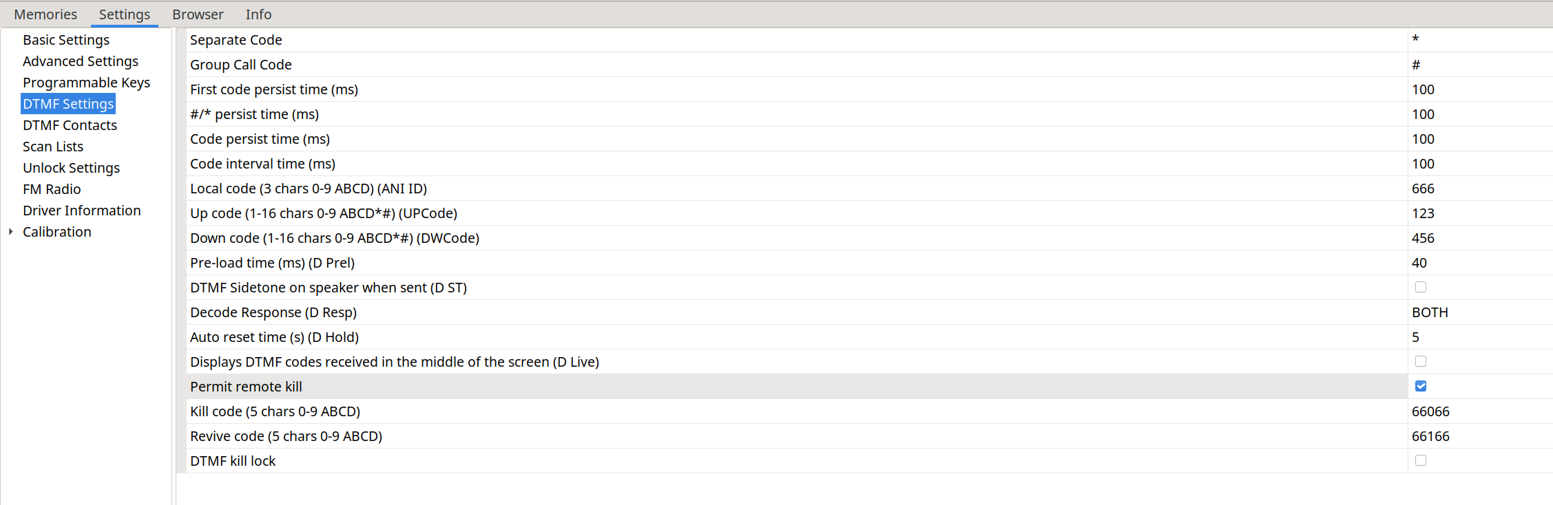
|
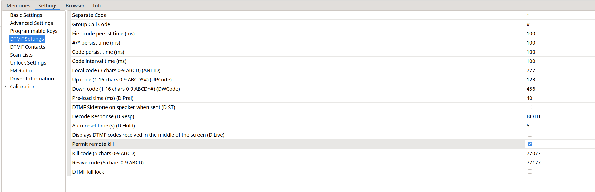
|
To kill radio 666 we must call: ANI ID * Kill code, in this case 666 * 66066
To revive it: ANI ID * Revive code, in this case 666 * 66166
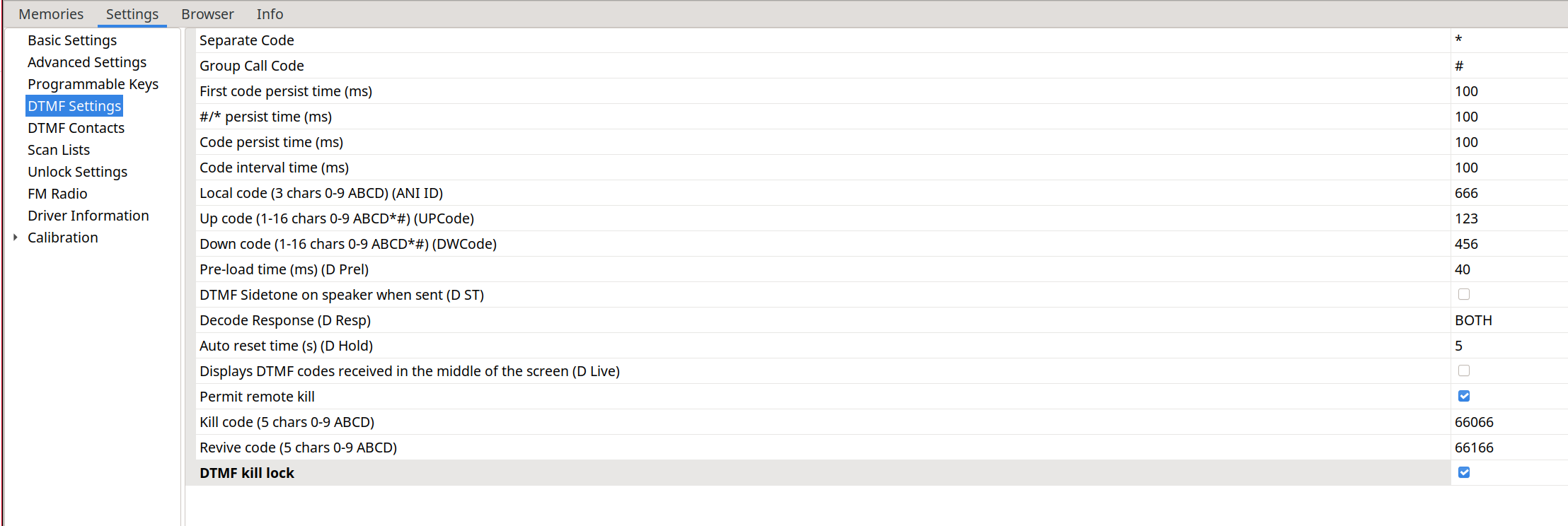
As we can see, neither the Kill code nor the Revive code seem to do anything; it simply interprets them as the reception of DTMF codes. If we enable the D Live (42) option, we can see them:
The DTMF kill lock option will have no effect whatsoever on the radio:
CHIRP:
Install CHIRP:
python3 -m venv chirp
cd chirp
pip install wxPython
pip install https://trac.chirp.danplanet.com/chirp_next/next-20240224/chirp-20240224-py3-none-any.whl
CHIRP is software that leaves a lot to be desired. Some time ago, native support for NUNU was added:
release v1.0.1 Feb 17, 2024
This driver is now added to the official CHIRP release. This will probably be the last release in this repository.
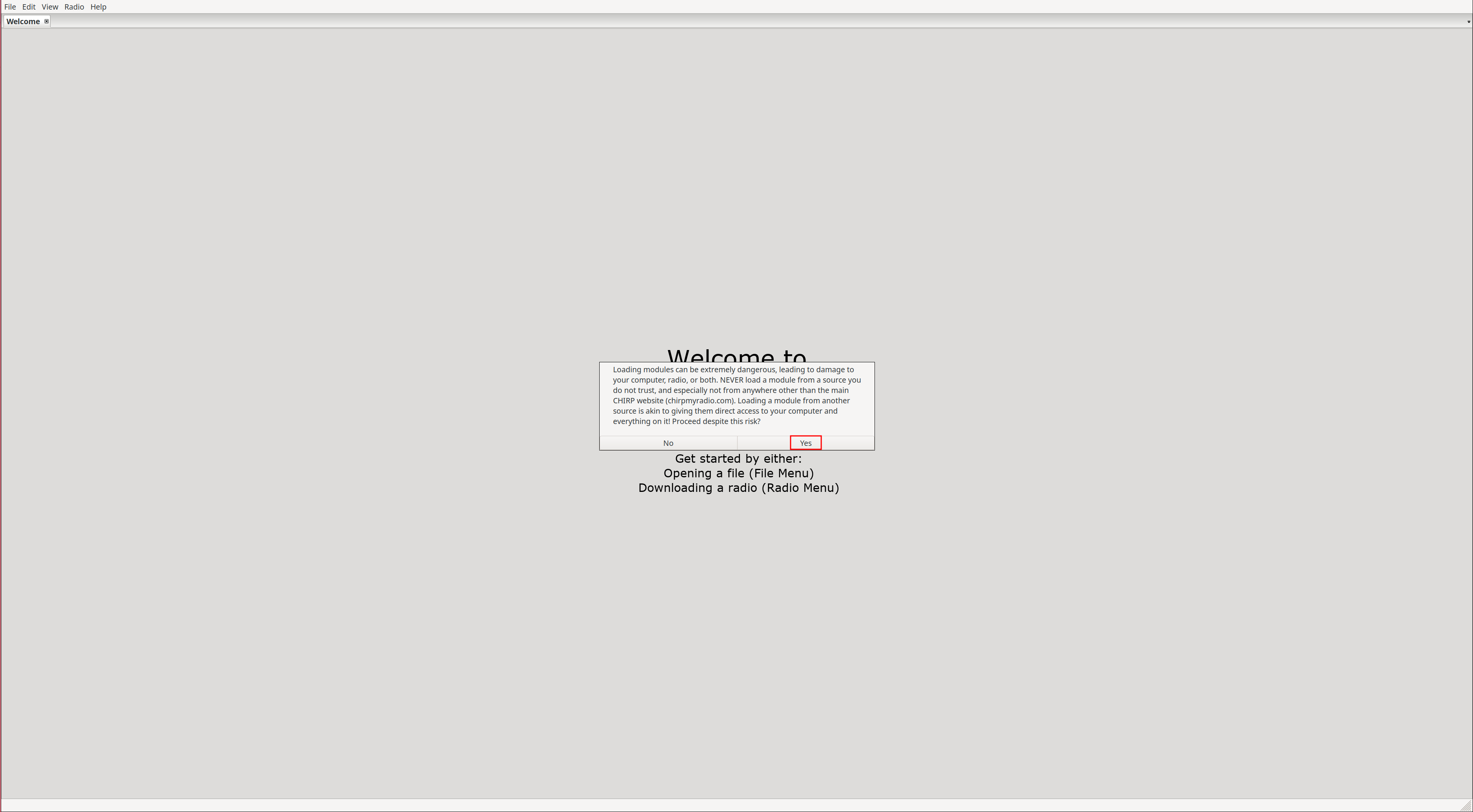
But later it broke, requiring the module to be loaded again using Developer mode:
Due to recent CHIRP update many custom firmwares (including this one) are not supported and require a custom uvk5-chirp-driver.
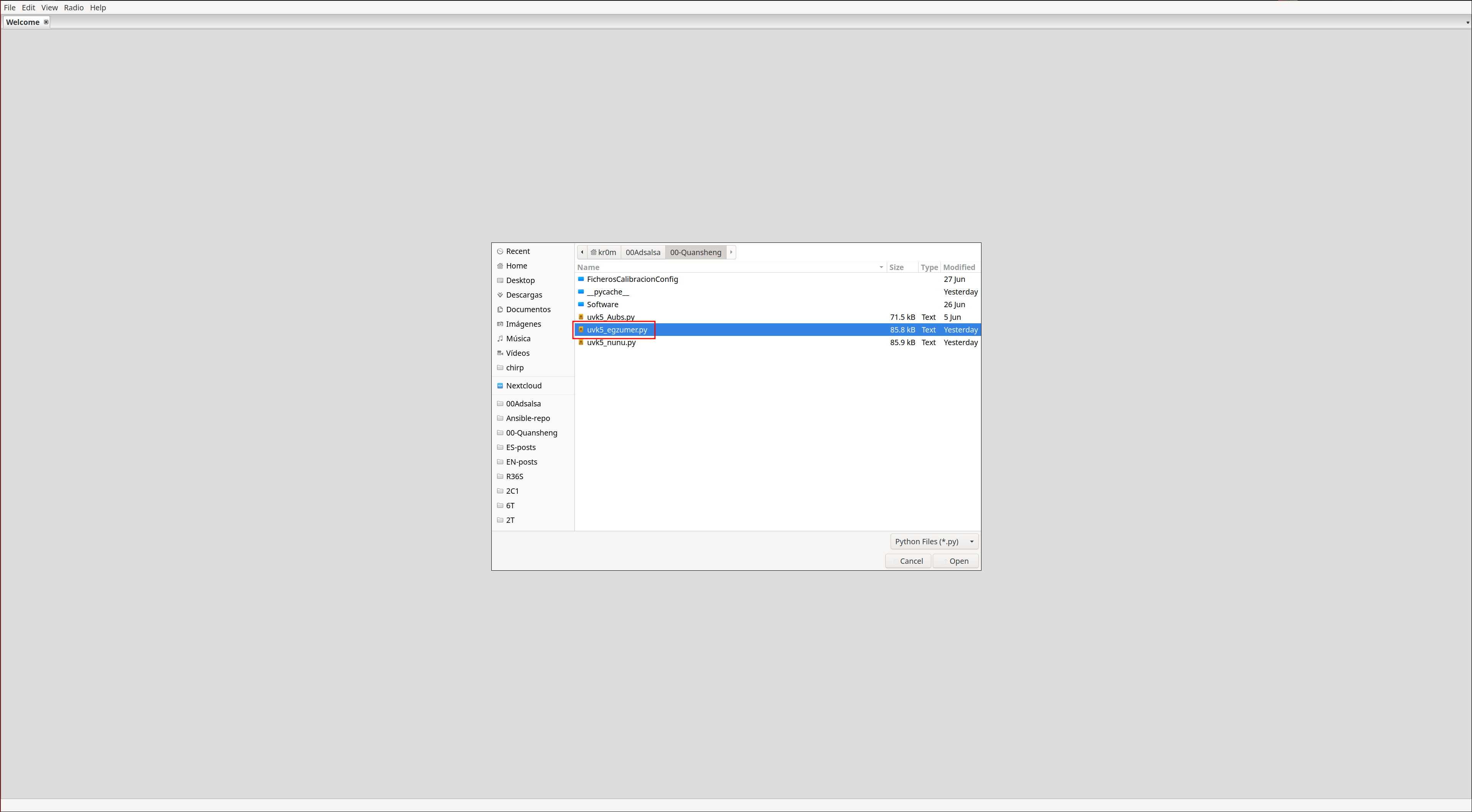
So we download that module :
wget https://raw.githubusercontent.com/kamilsss655/uvk5-chirp-driver/refs/heads/main/uvk5_egzumer.py
Enable Developer mode:
Help -> Developer mode
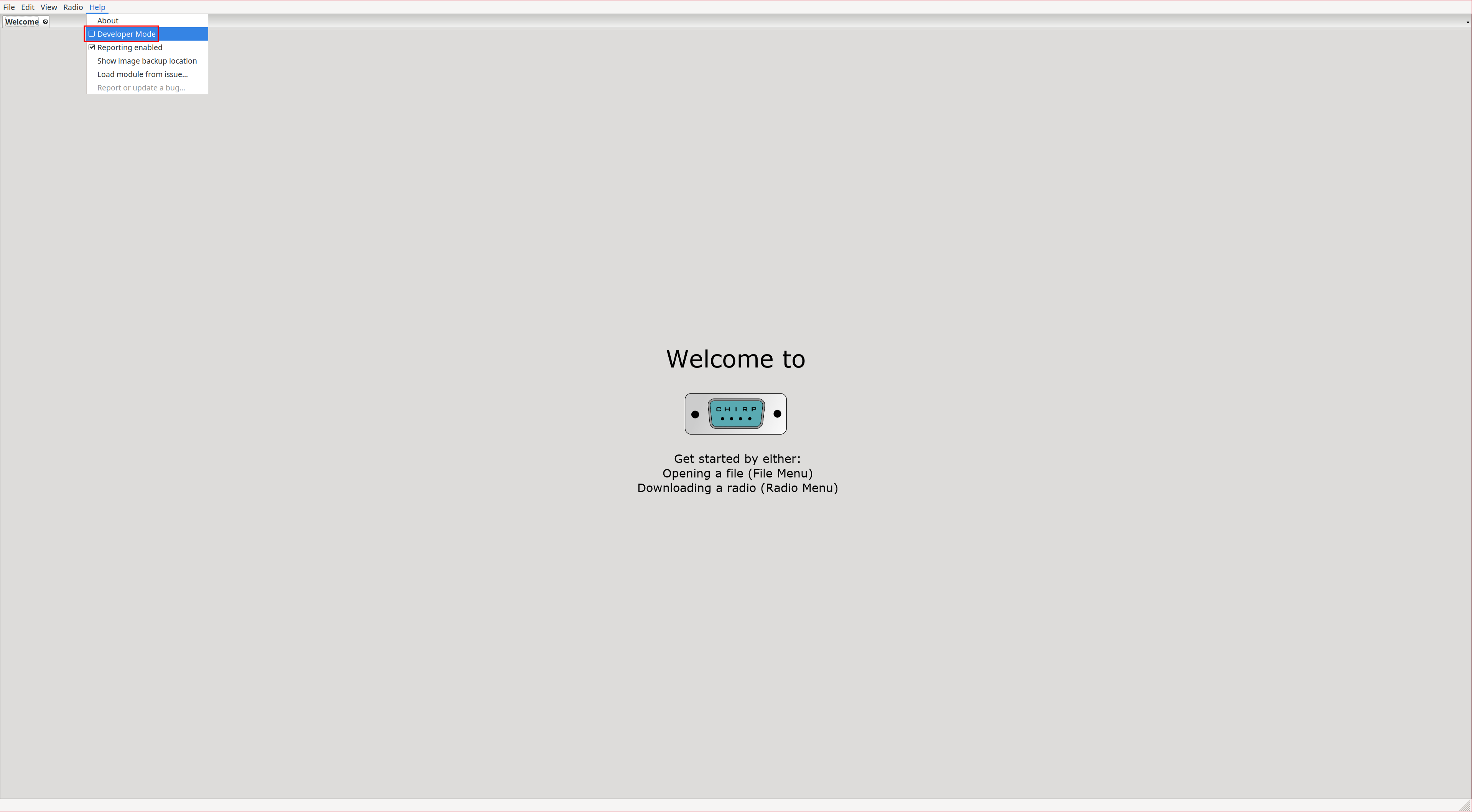
|
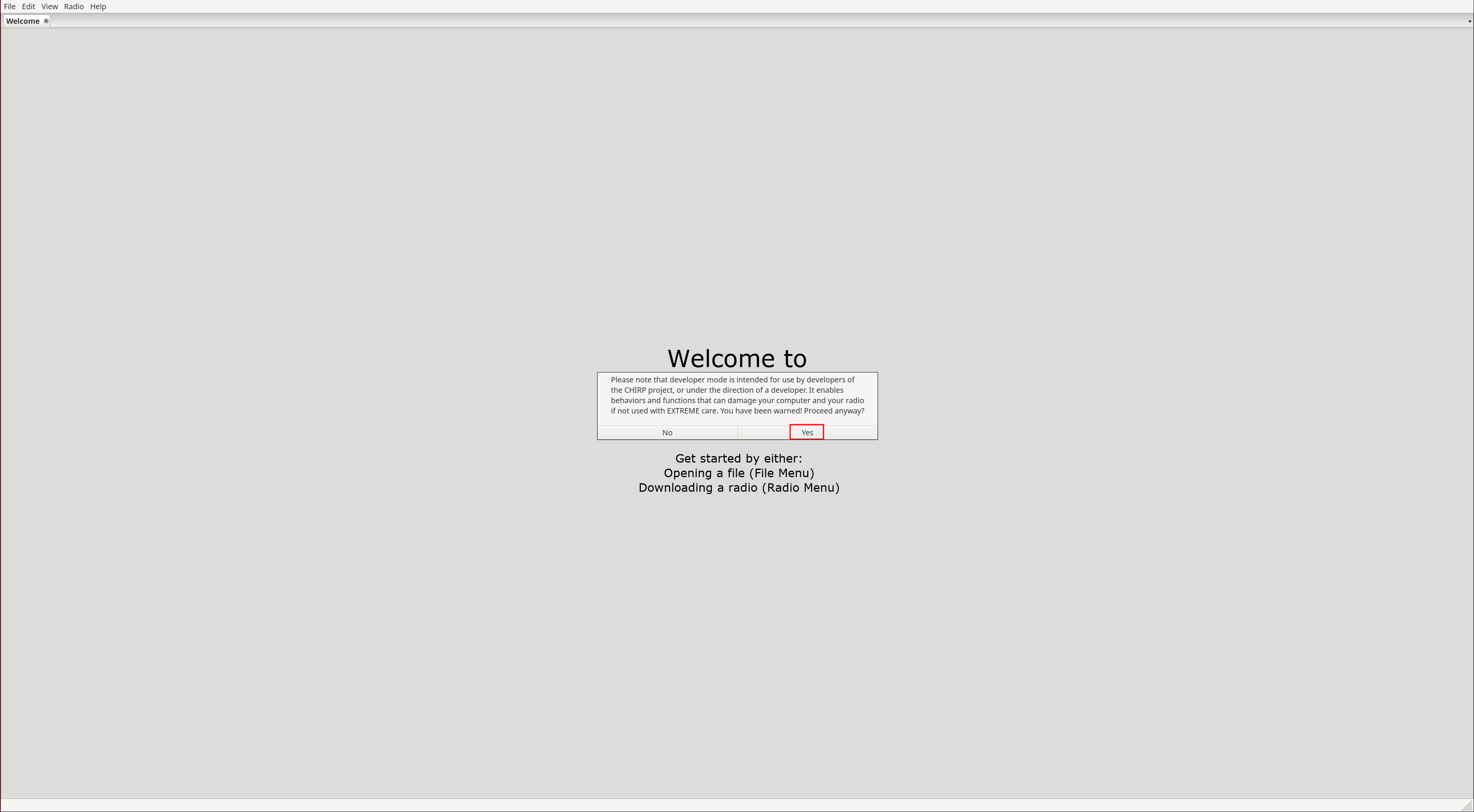
|
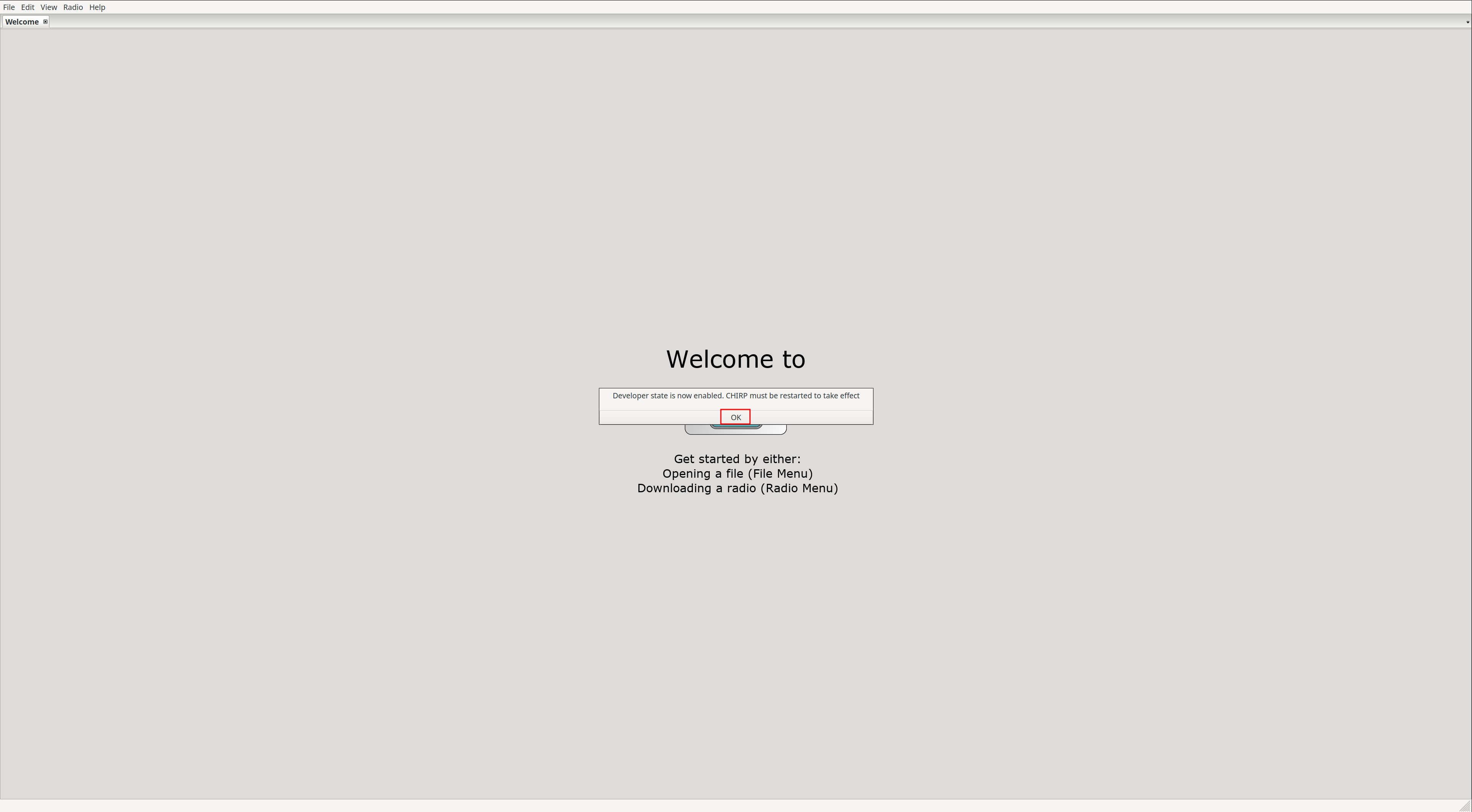
|
After restarting, we can load the driver:
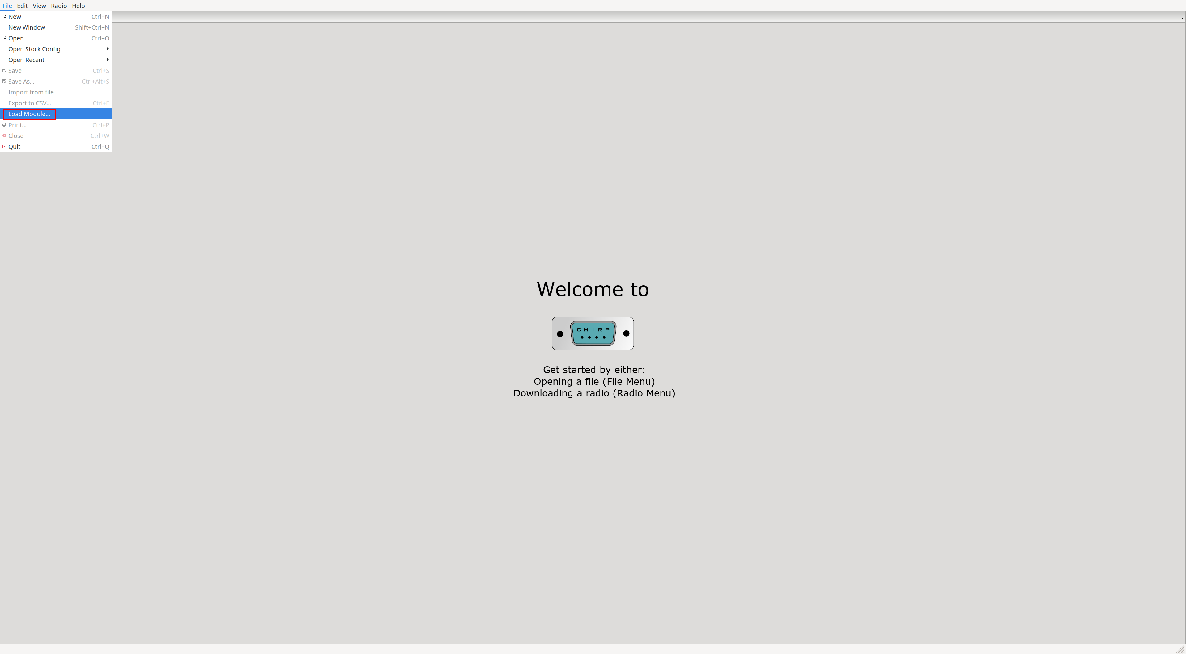
File -> Load Module...
|
|
|
NOTE: CHIRP is fairly poor software. For example, if we select a value from a dropdown but do not remove focus from the parameter, it will NOT be applied. That is, if we upload the configuration to the radio, that change will not have been applied.
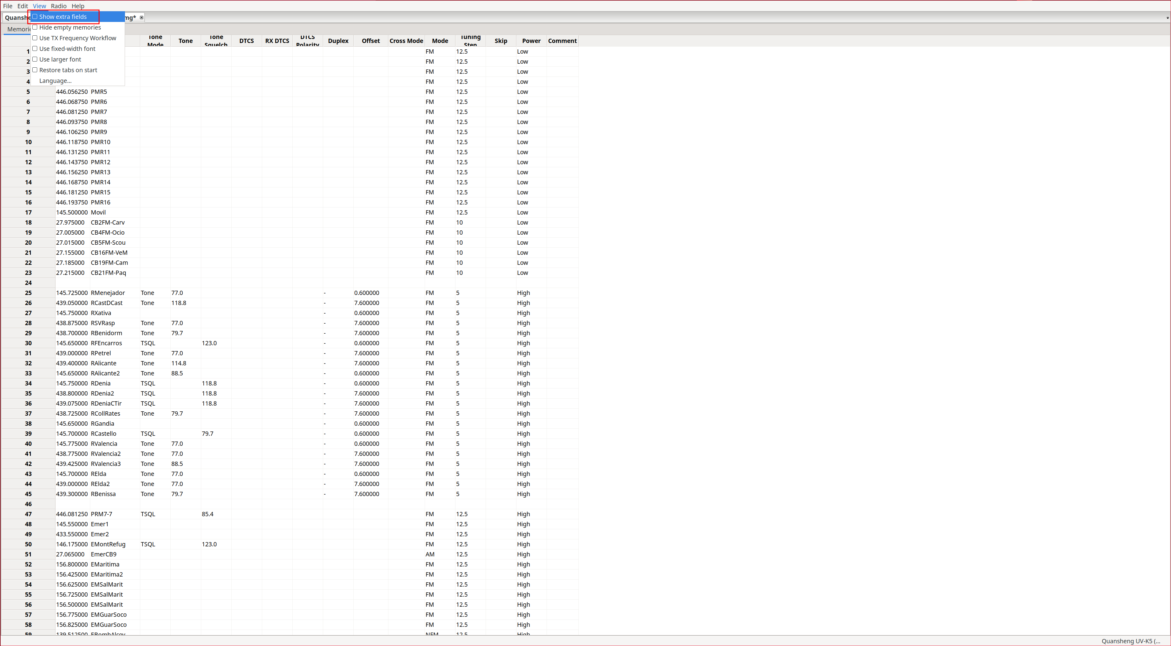
Extra fields:
The first step before configuring anything is to enable Extra fields, as this allows us to view all NUNU configuration parameters.
View -> Show extra fields
|
|
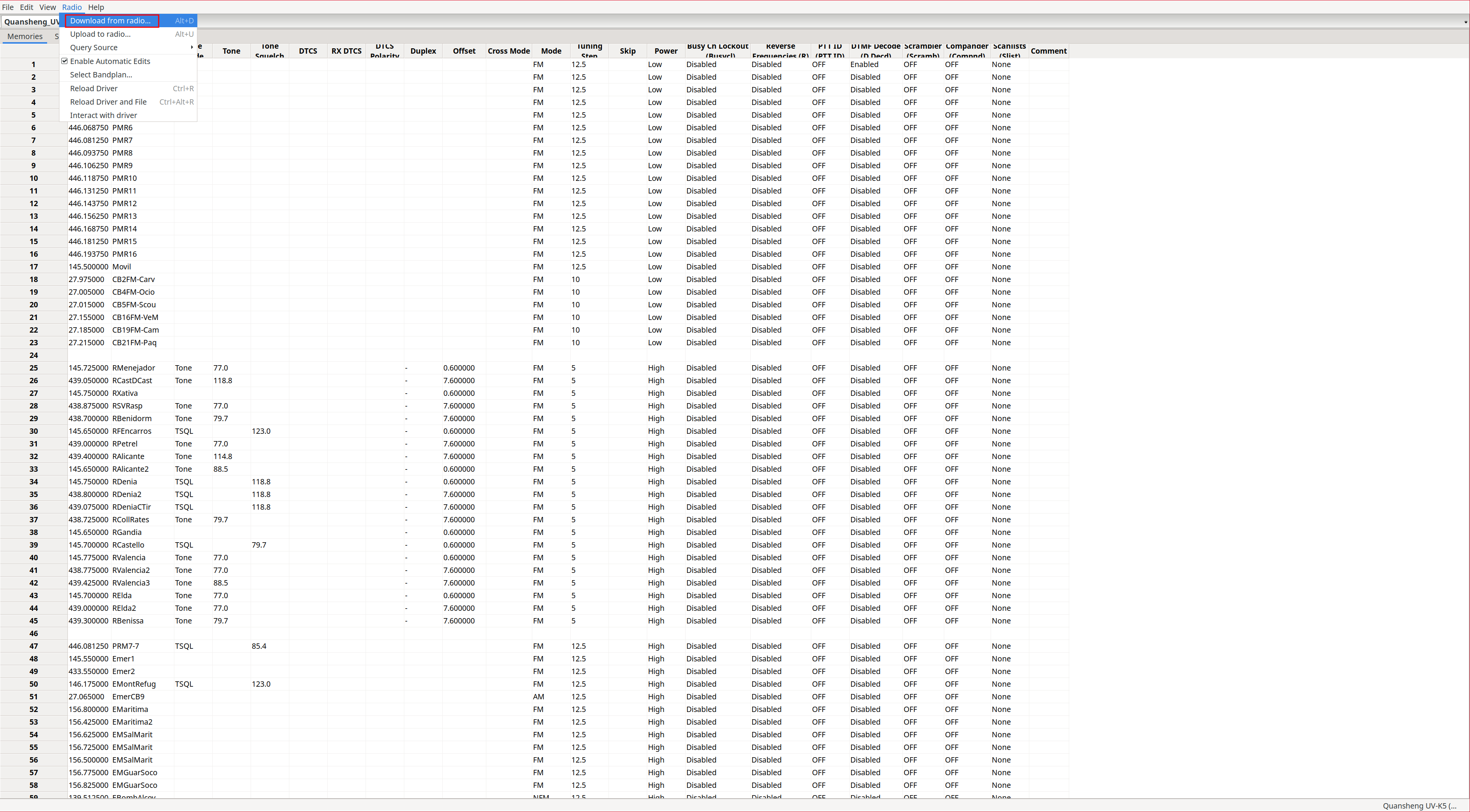
Connect to the radio:
Radio -> Download from radio...
Model: UV-K5 (egzummer)
|
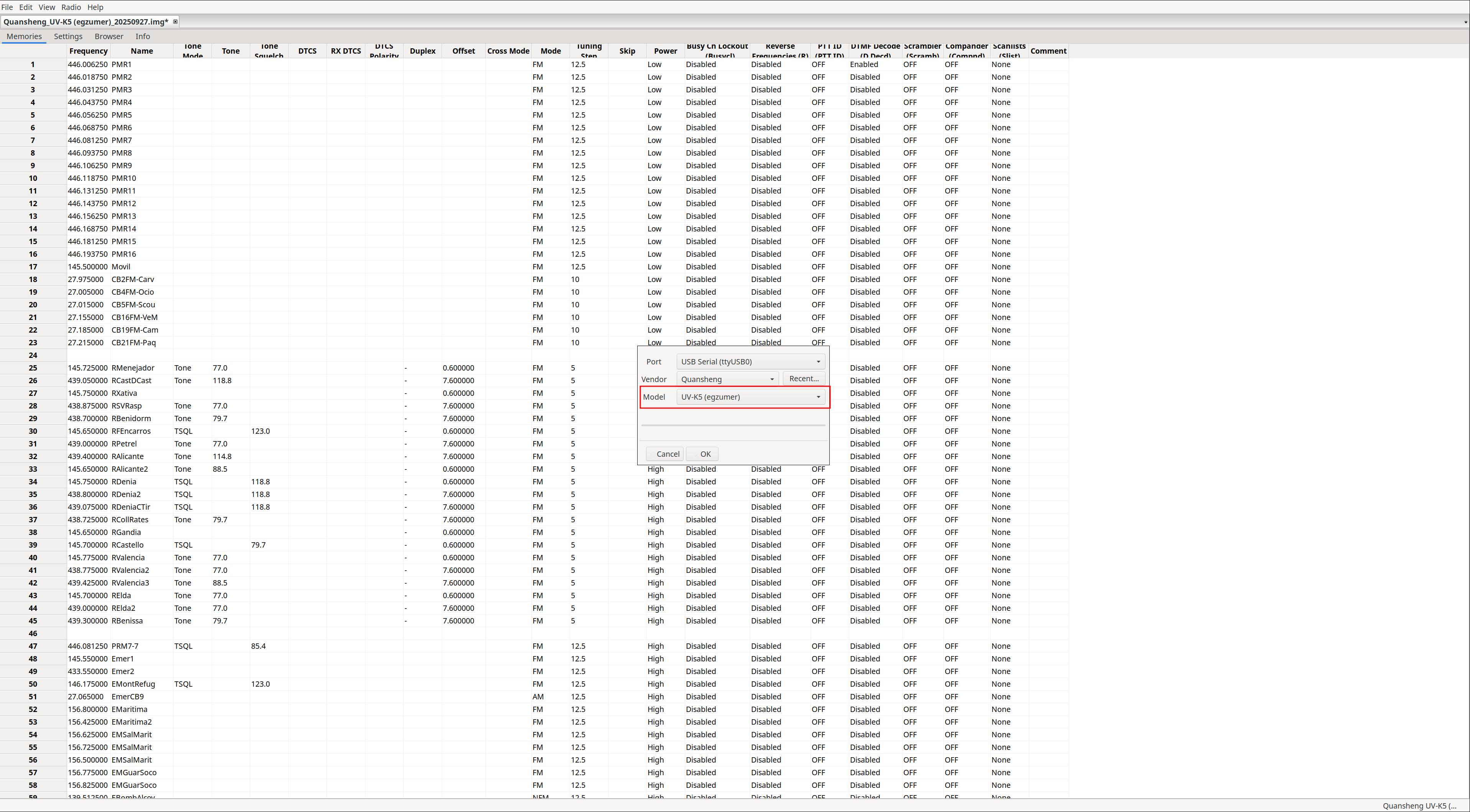
|
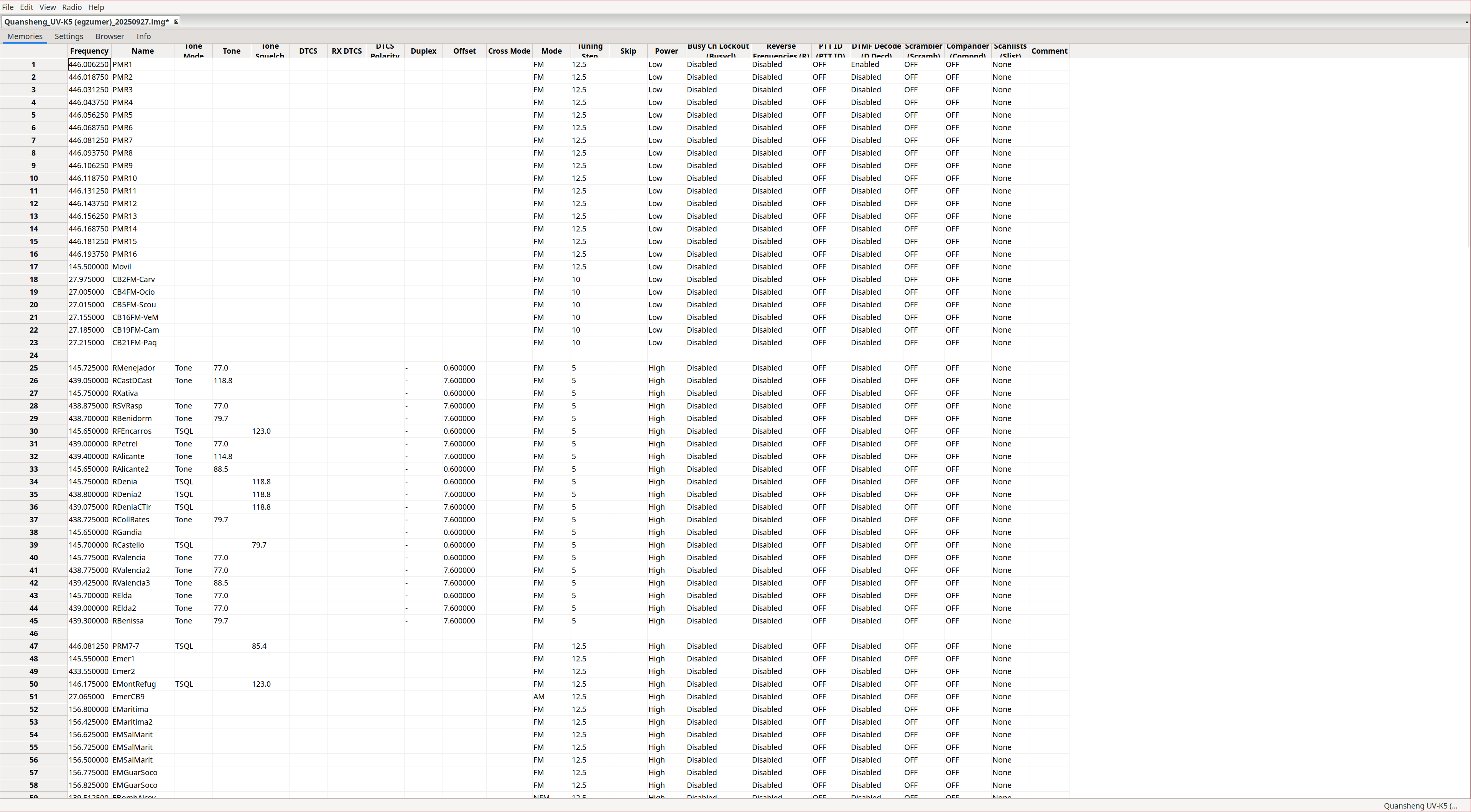
Channel list:
The channel list will be displayed. In my opinion, the interface leaves much to be desired, as it is very difficult to understand what each field represents. It would have been much simpler to map one column per walkie menu option, as
CPS
does. Despite its lack of intuitiveness, I will try to explain what
each parameter does
.
There are some options such as Mode that, in CHIRP, only allow FM, NFM, AM, NAM, and USB, while the walkie supports many more options via Bandw (2) and Demodu (14).
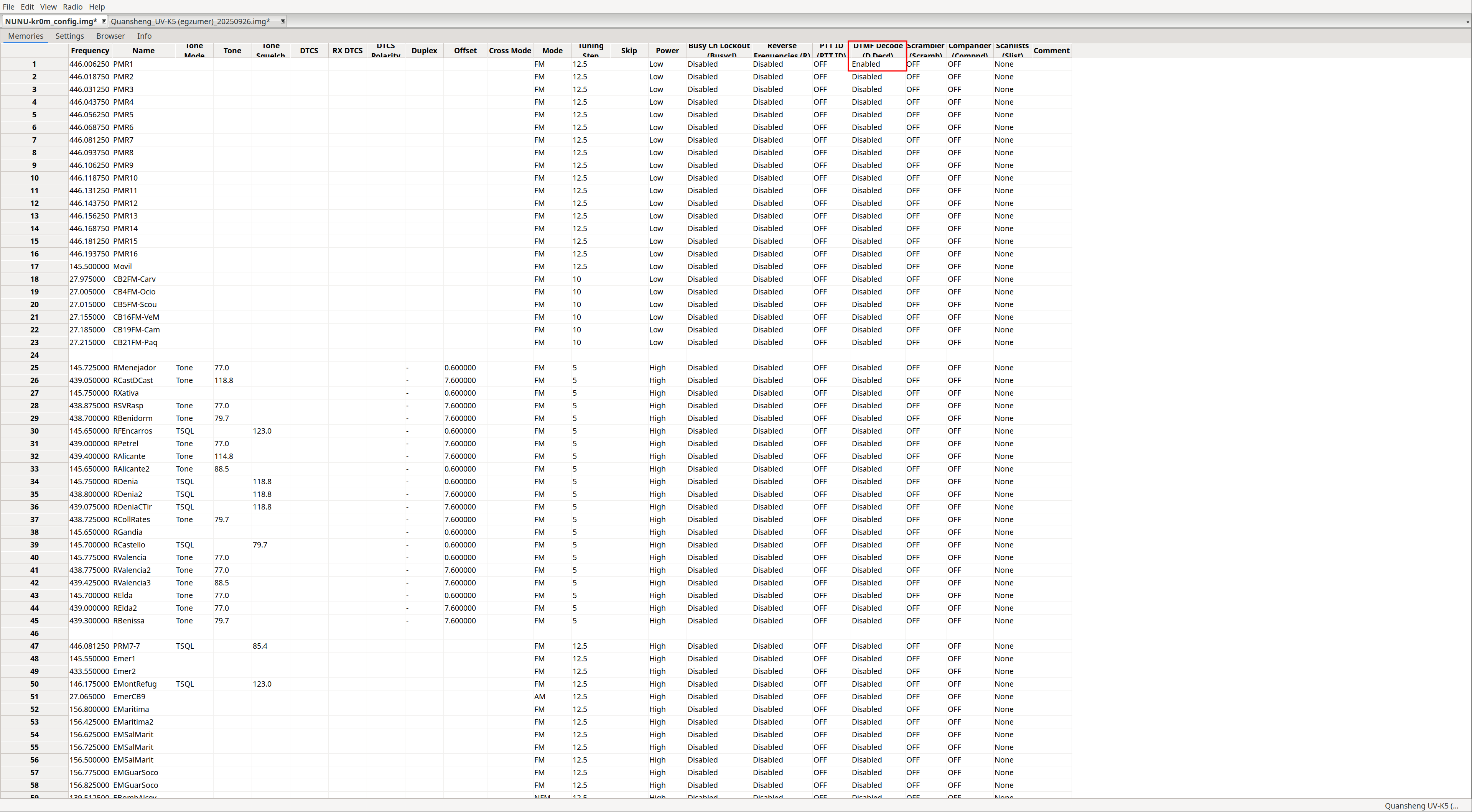
On the other hand, the PTTID and DTMF Decode parameters can only be changed from CHIRP, although these options are effectively useless because DTMF support in NUNU is very limited due to
this
.
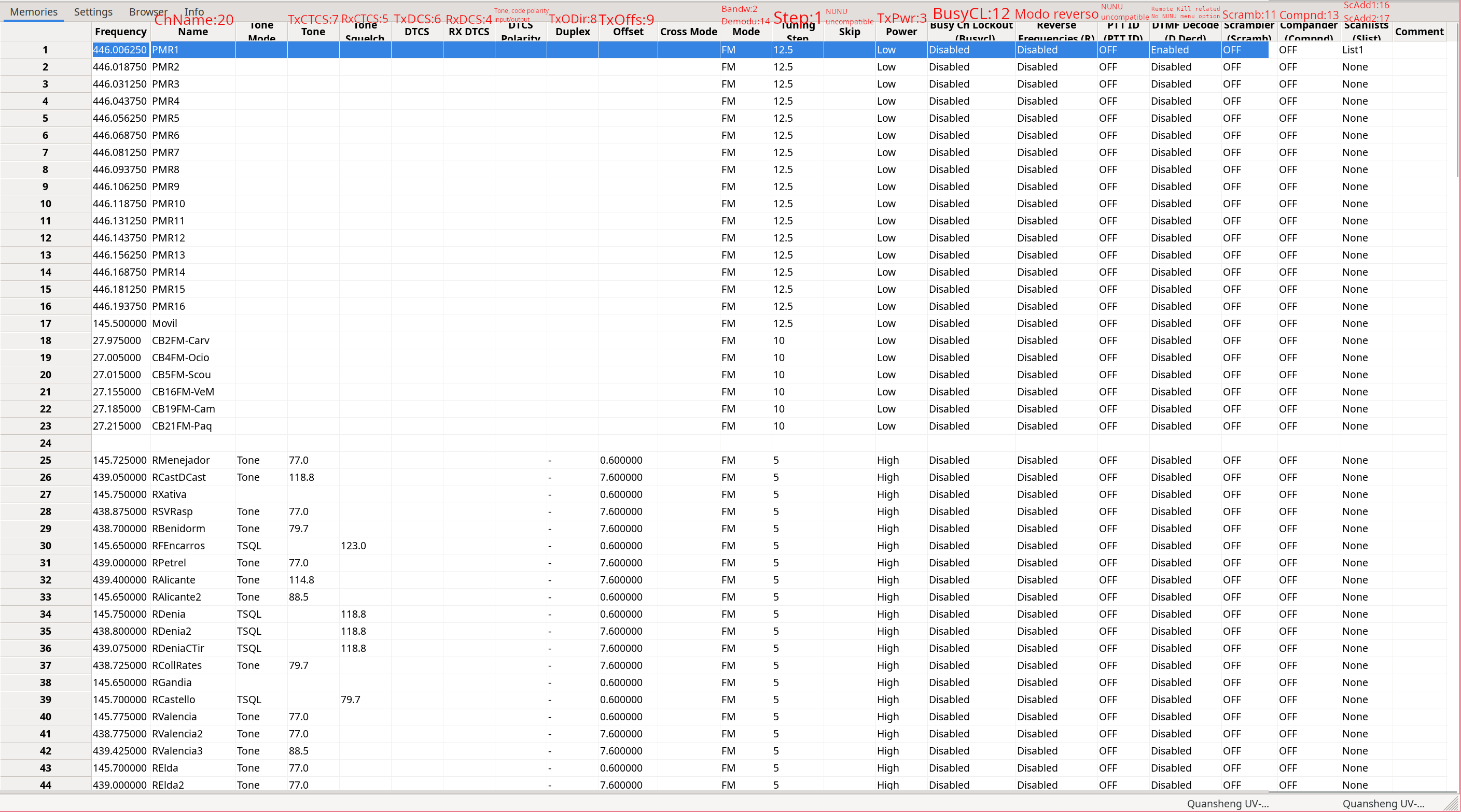
In the screenshot we can see the channel list with the corresponding walkie menu parameters highlighted in red:
The DTCS Polarity option specifies the output/input polarity of the
tone/code
. Tones only allow positive polarity (N), while digital codes allow both positive (N) and negative (R):
| Value | TX polarity | RX polarity |
|---|---|---|
| NN | Positive | Positive |
| NR | Positive | Negative |
| RN | Negative | Positive |
| RR | Negative | Negative |
The Tone Mode option can take one of the following values:
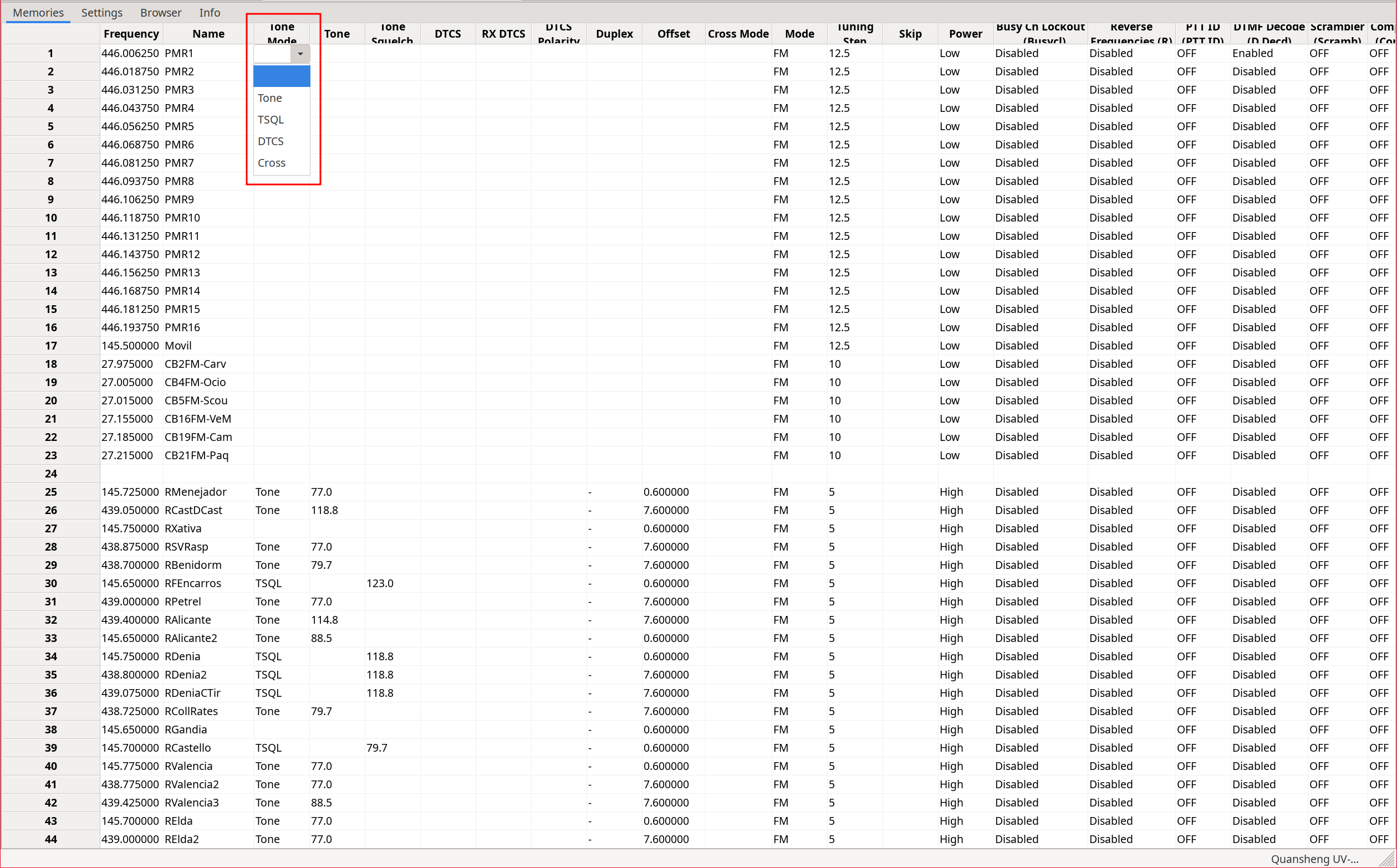
| Value | TX code/tone | RX code/tone |
|---|---|---|
| None | No tone/code assigned | No tone/code assigned |
| Tone | Tone: Tone column | No tone/code assigned |
| TSQL | Tone: ToneSquelch column | Tone: ToneSquelch column |
| DTCS | Code: DTCS column | Code: DTCS column |
| Cross | Mixed configuration | Mixed configuration |
Depending on the selected option, the associated field will be populated with a predefined value.
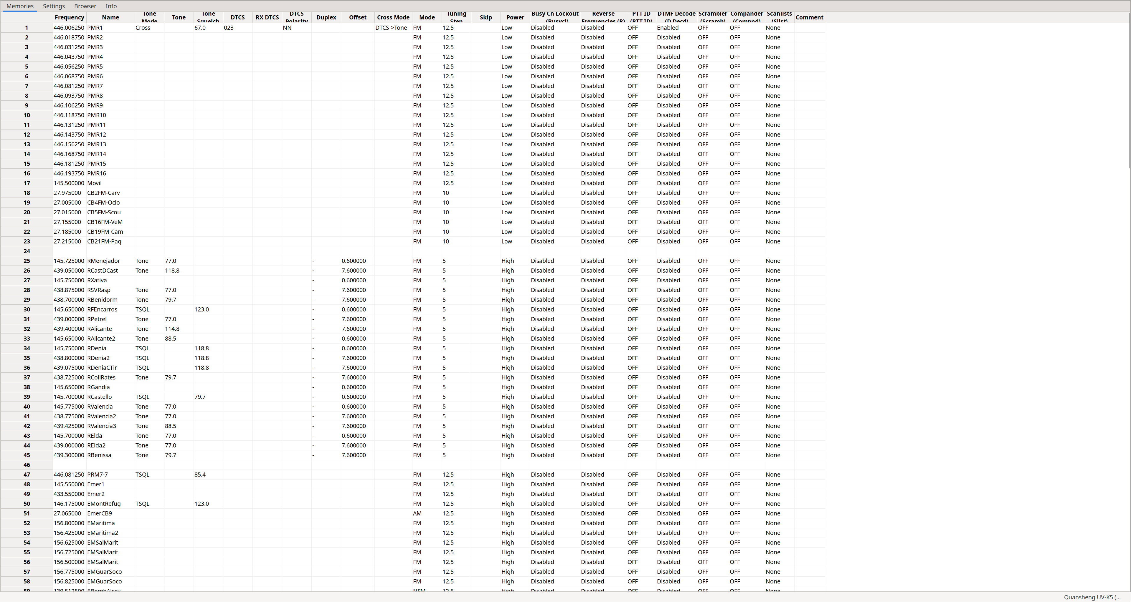
If we choose Cross, a series of windows will appear where we can perform mixed configurations. That is, we can choose whether to use tones or codes independently for input and output. This field depends on another column: Cross Mode.
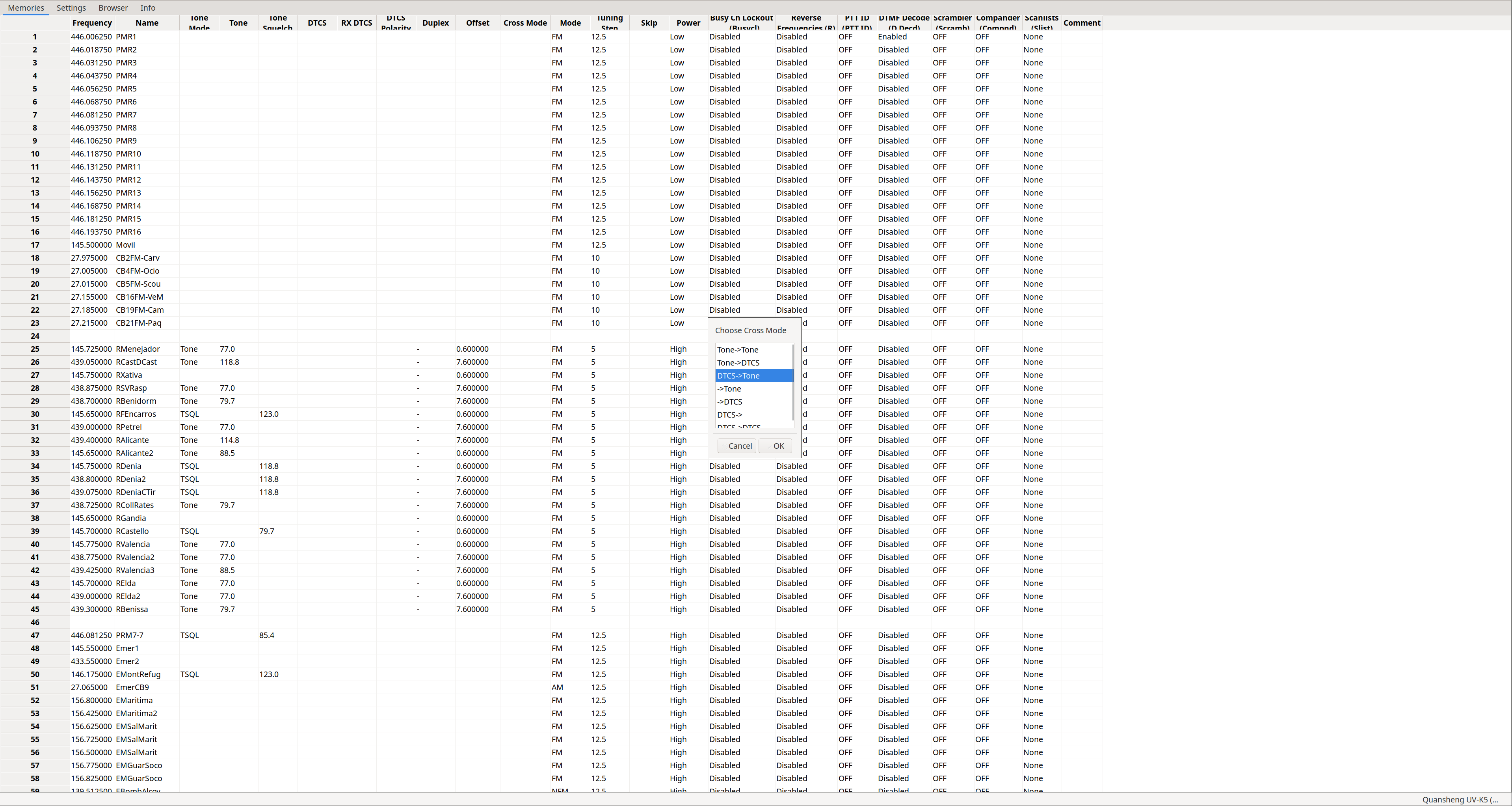
|
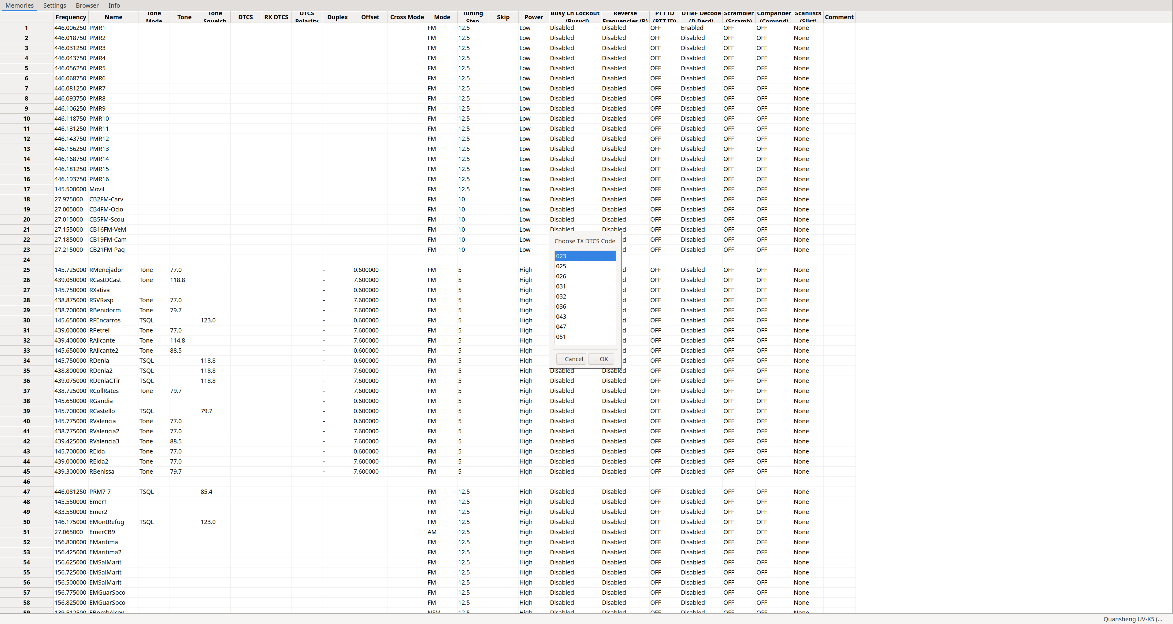
|

|
|
The Cross Mode column will be set according to whether we chose tones or codes. The first field indicates transmission, the second reception:
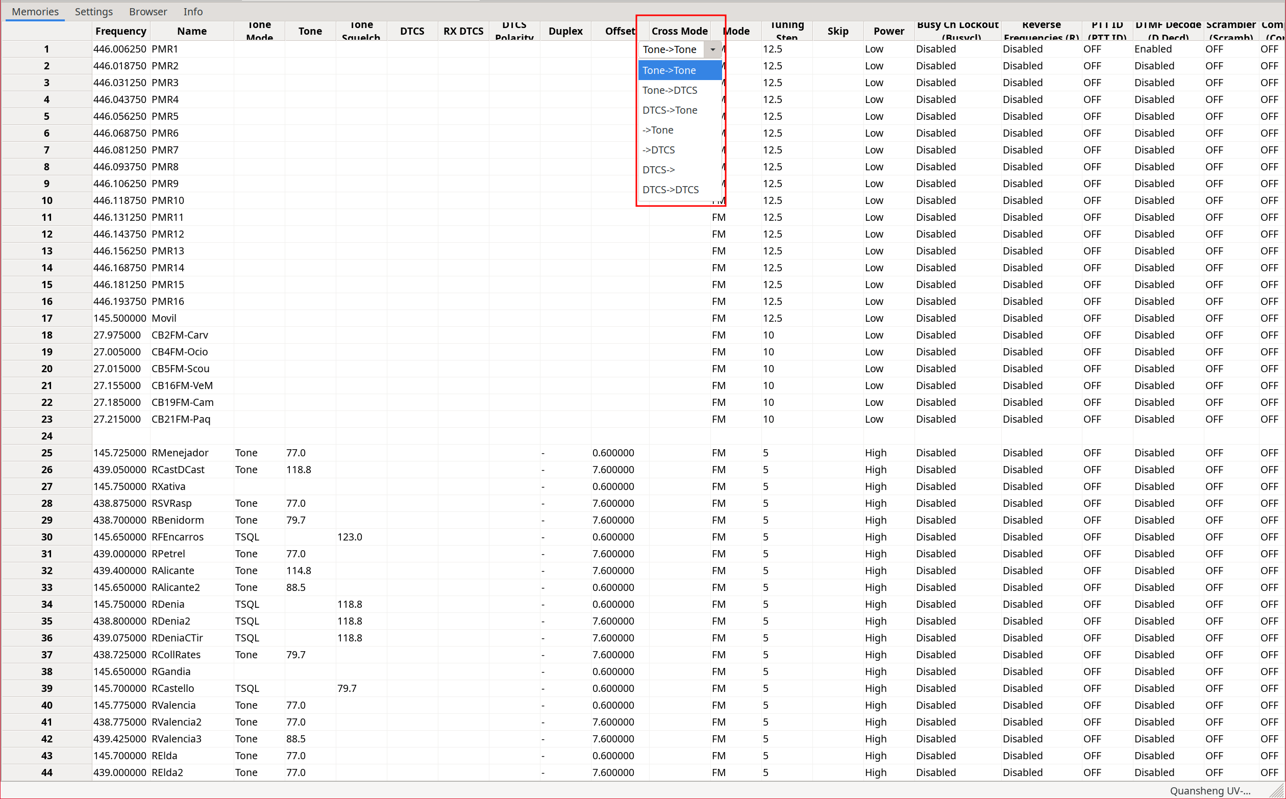
Depending on the values chosen in the windows that appear when selecting Tone Mode: Cross, we will have:
| Value | TX code/tone | RX code/tone |
|---|---|---|
| Tone -> Tone | Tone: Tone column | Tone: ToneSquelch column |
| Tone -> DTCS | Tone: Tone column | Code: RX_DTCS column |
| DTCS -> Tone | Code: DTCS column | Tone: ToneSquelch column |
| -> Tone | No tone/code assigned | Tone: ToneSquelch column |
| -> DTCS | No tone/code assigned | Code: RX_DTCS column |
| DTCS -> | Code: DTCS column | No tone/code assigned |
| DTCS -> DTCS | Code: DTCS column | Code: RX_DTCS column |
NOTE: For some reason the Tone -> option is missing. Typical CHIRP behavior. I assume this will be fixed over time, remembering that Quansheng support is still experimental.
Band list:
Just like with
CPS
, CHIRP also allows defining the start and end of each band.
To modify these parameters, scroll to the very bottom of the channel list:
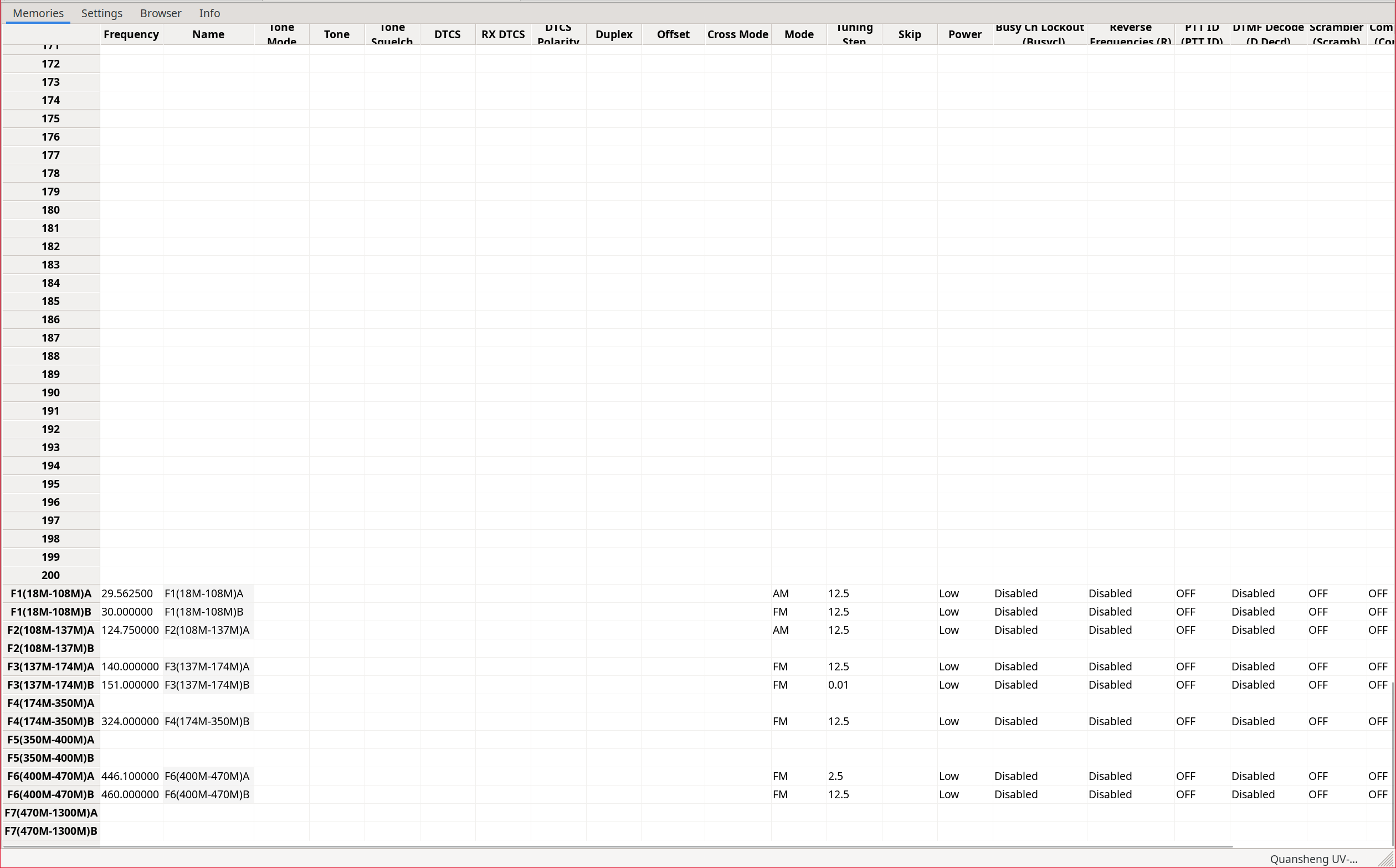
Modifying these parameters changes the frequency limits when scanning within a band and the default band parameters such as tones/codes , bandwidth, transmit power, and others. Of course, these parameters can always be modified on the fly from the walkie menu.
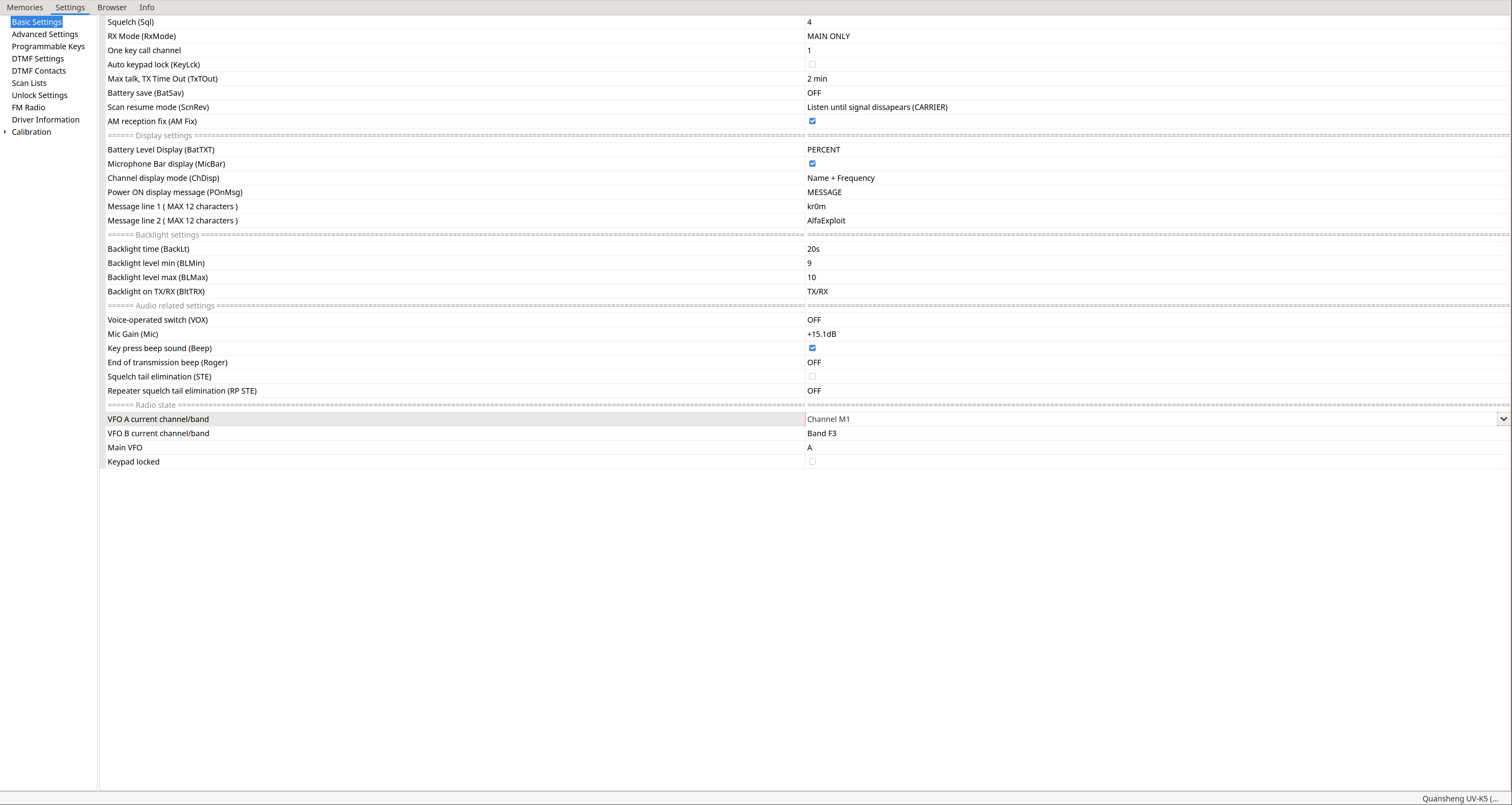
Settings:
In the Settings tab we can find the rest of the configuration. Keep in mind that the driver is a modification of EGZUMER and has not been fully adapted to NUNU, so some sections shown do not apply.
Basic Settings: As we can see, NUNU has taken the trouble to indicate which walkie parameter corresponds to each option.
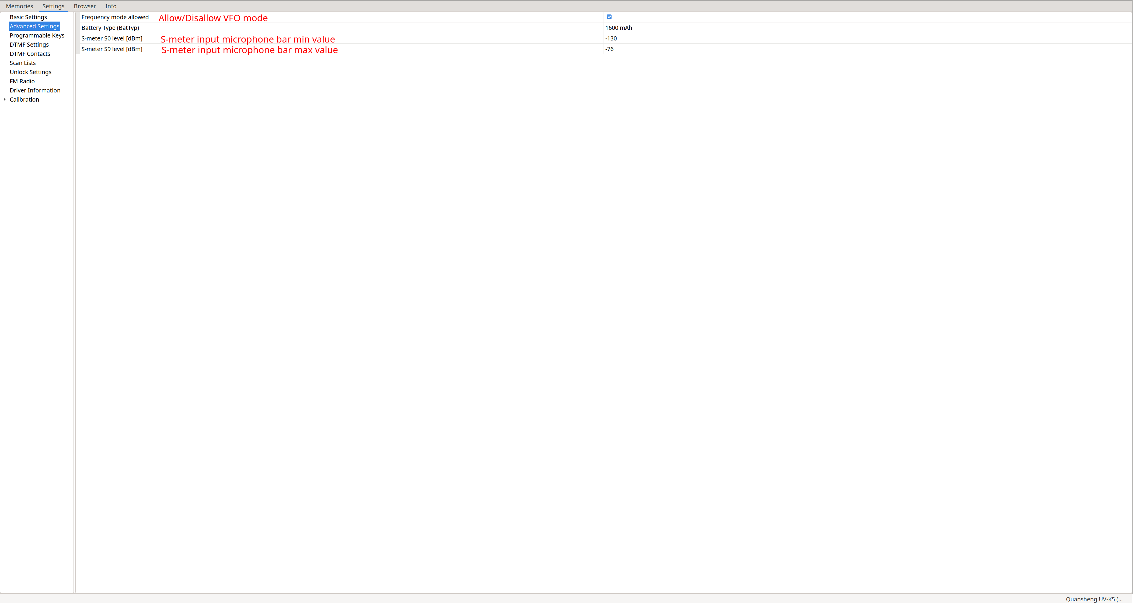
Advanced Settings:
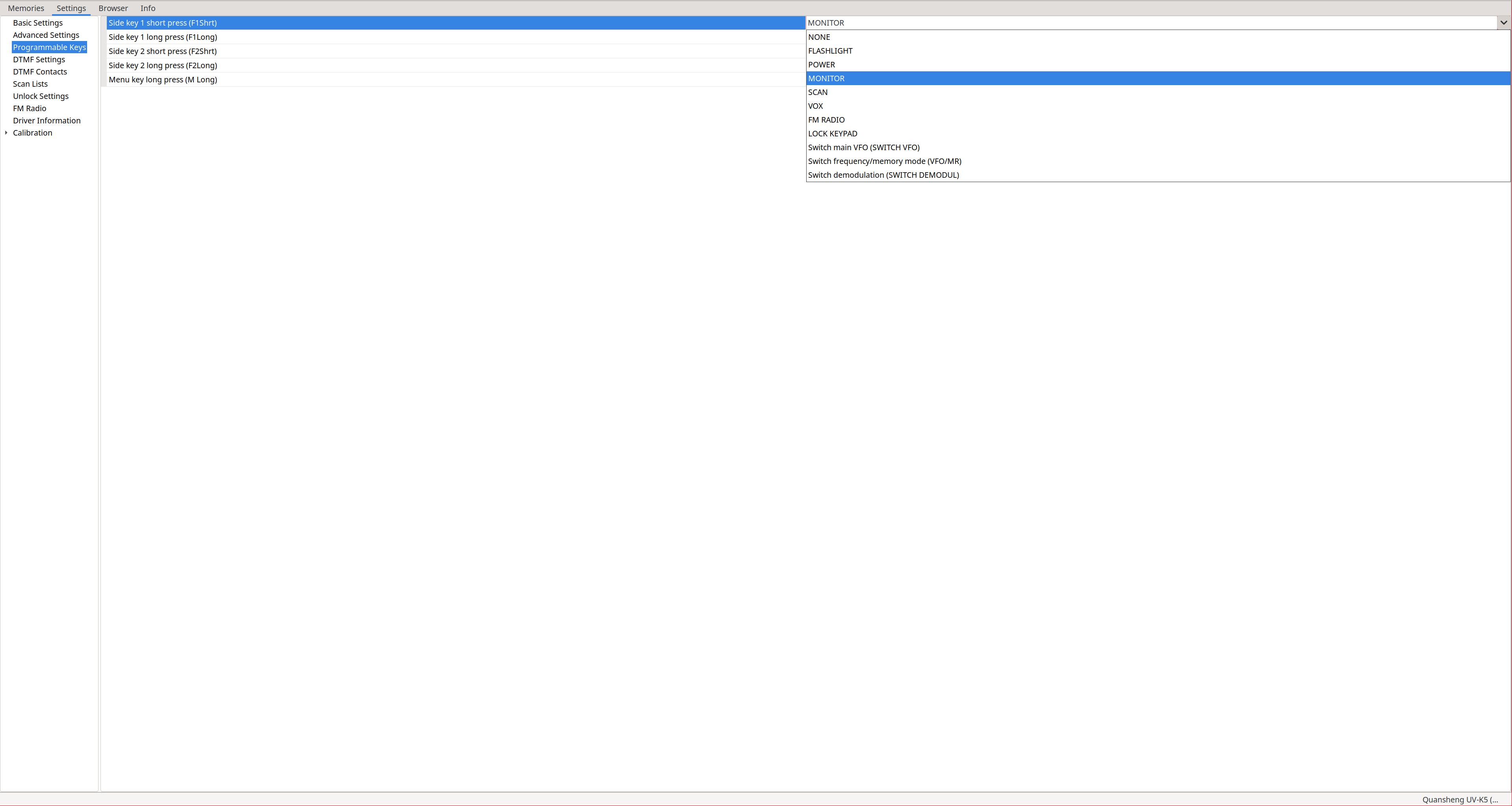
Programmable keys: SideKey configuration.
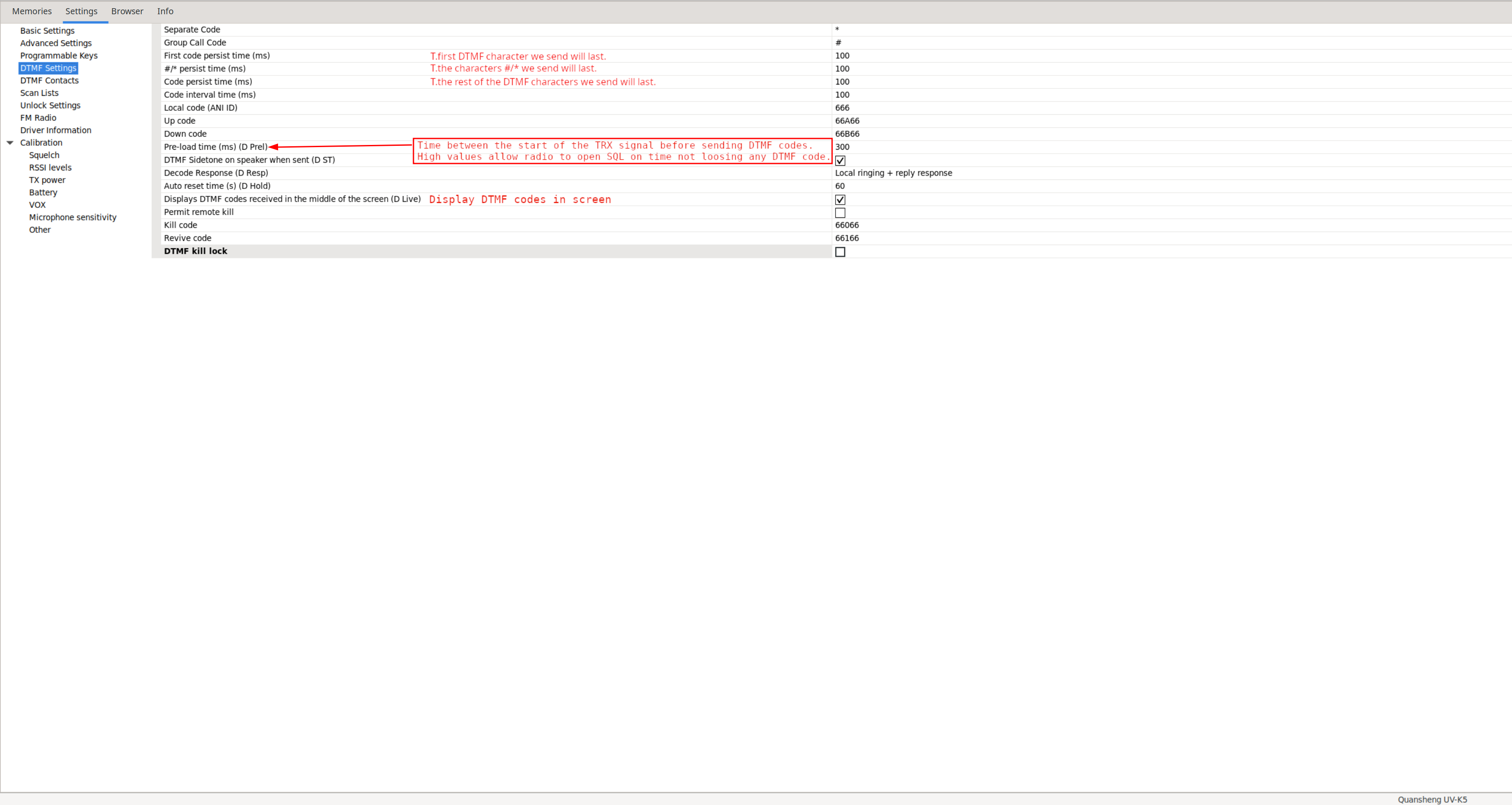
DTMF Settings: None of these parameters (except those already explained) make sense in NUNU due to
this
.
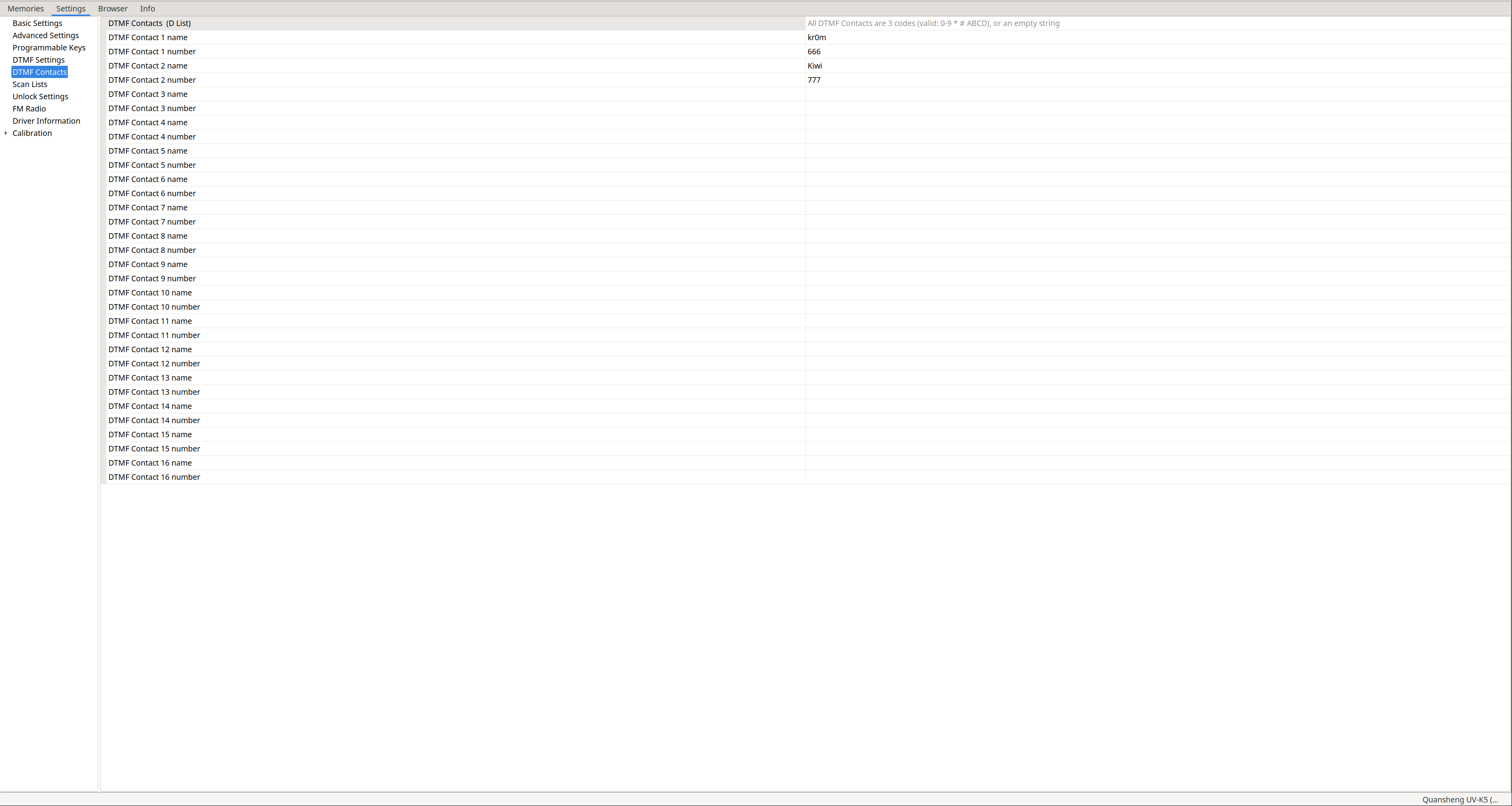
DTMF Contacts: DTMF contact configuration,
not applicable in NUNU
.
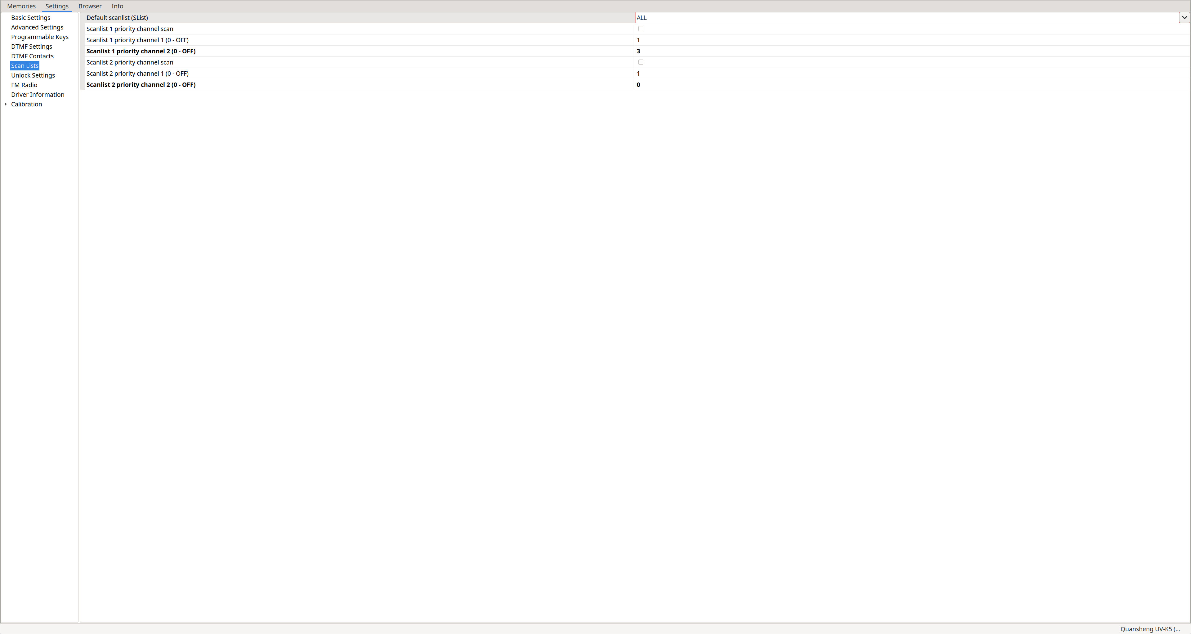
Scan Lists: From this section we can only assign the default scan list, enable/disable scan priority, and configure the two priority channels of each list. These channels are scanned more frequently than non-priority ones. This is useful when scanning many channels without missing activity on a priority channel while the radio is busy scanning others. To edit the lists, use the Memories tab after enabling extra fields: View -> Show extra fields
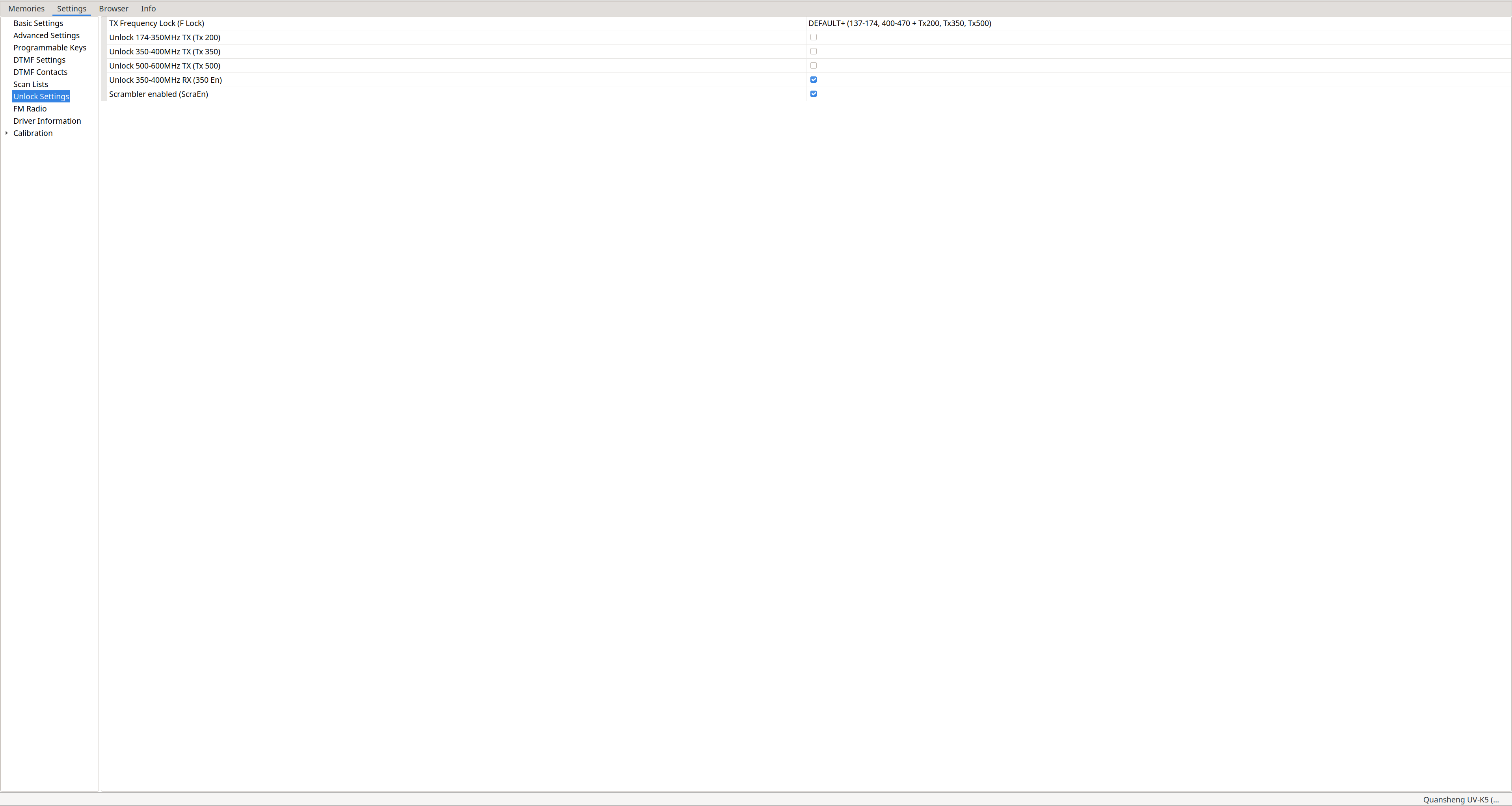
Unlock Settings: Allows
unlocking transmission on frequencies
outside the amateur radio bands and enabling/disabling
scrambling
, just like from the extended menu when
calibrating the battery
.
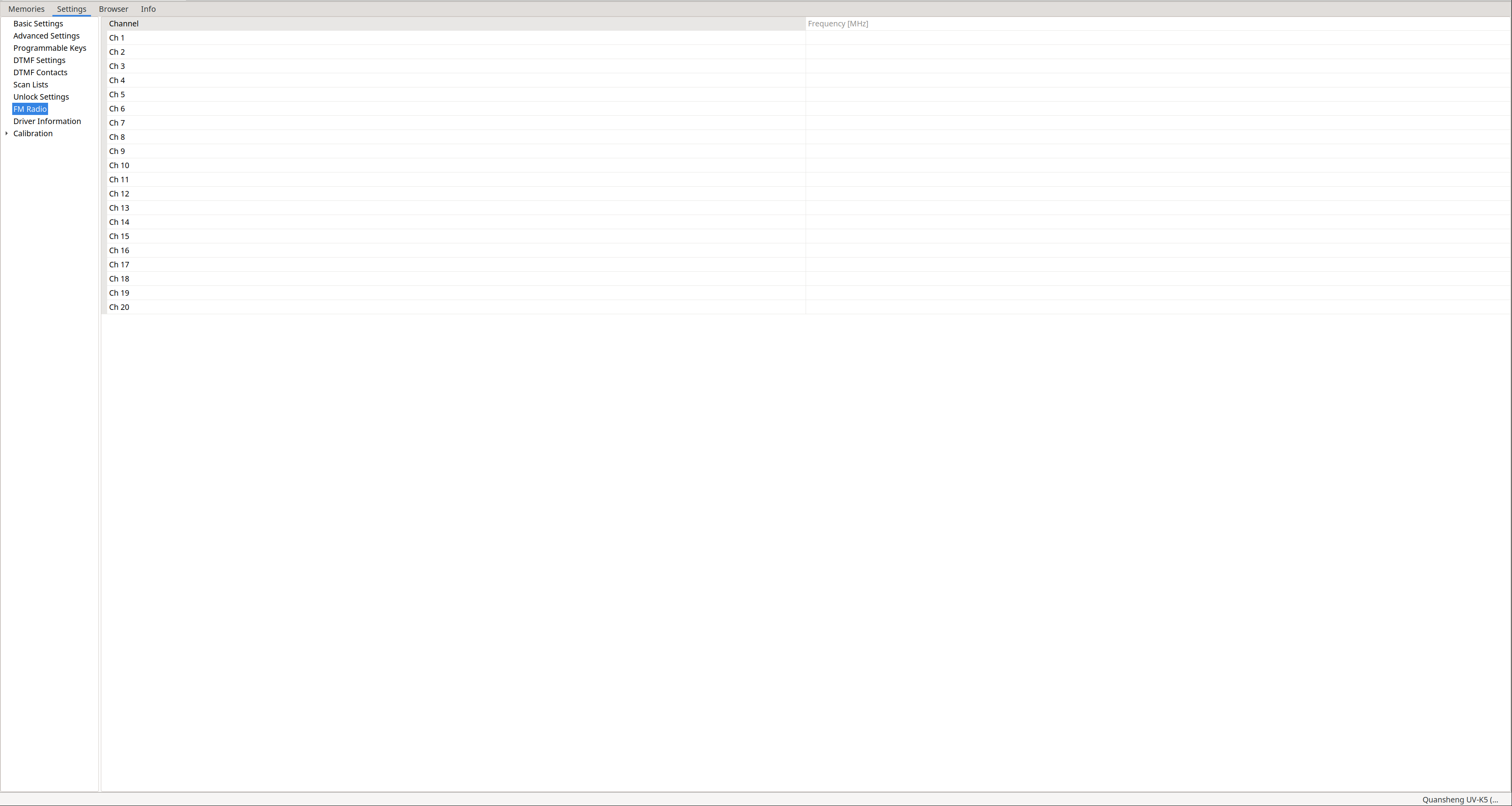
FM Radio: Not applicable in NUNU, since broadcast FM radio features have been
significantly reduced
.
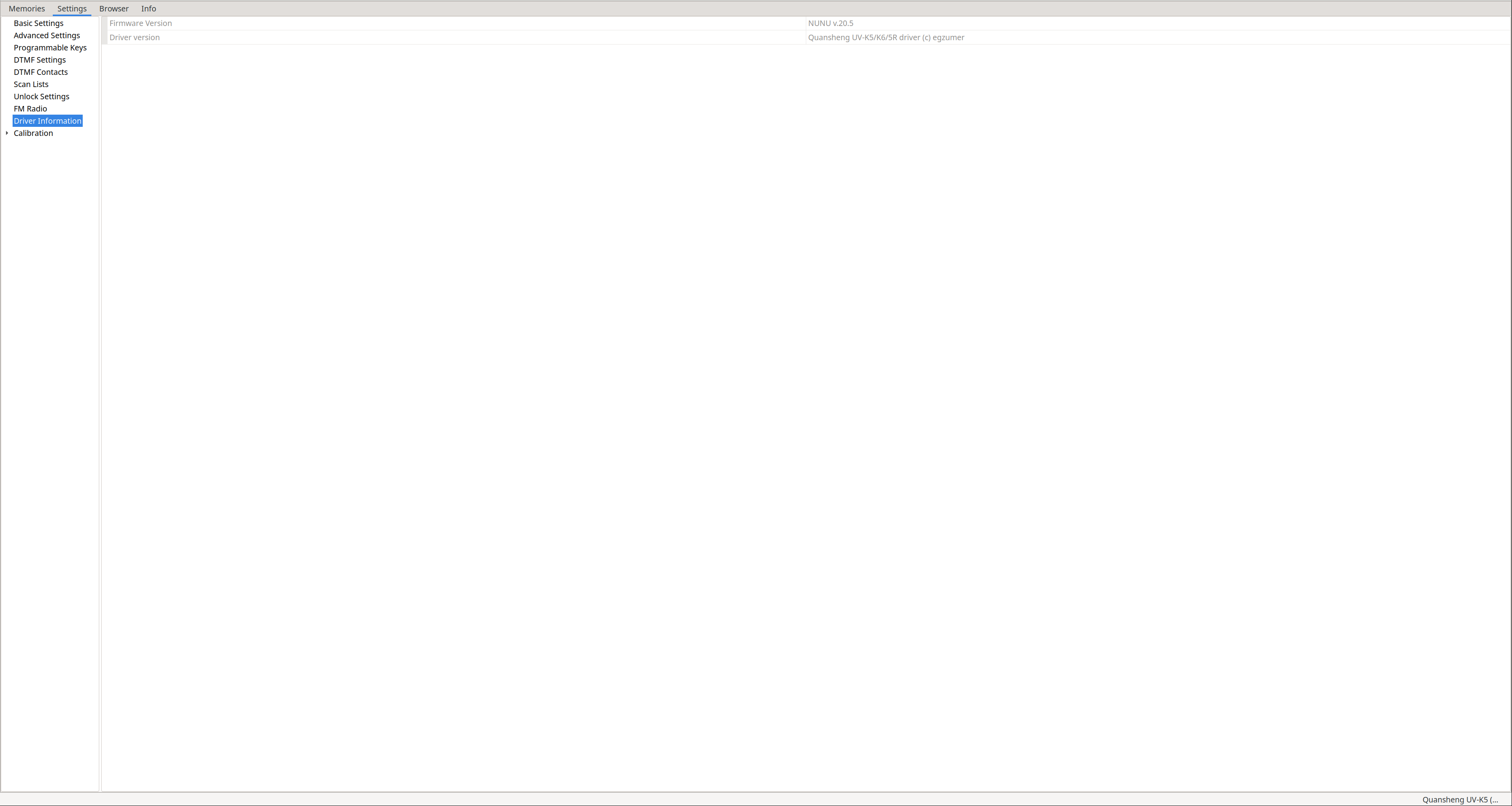
Driver information: Displays the firmware version.
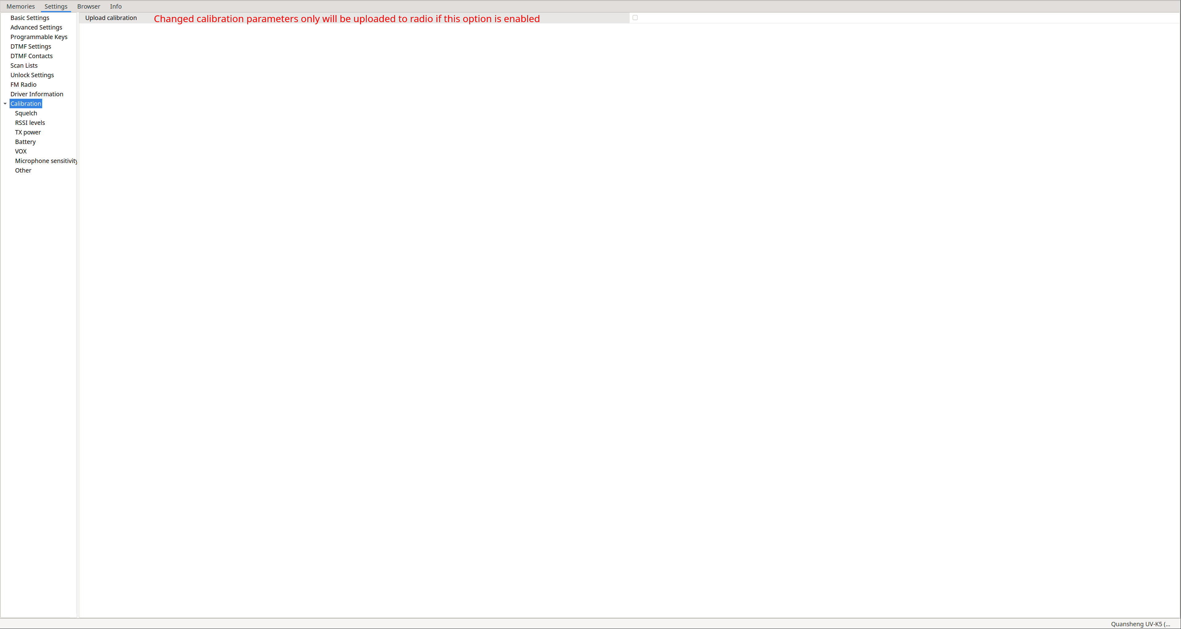
Calibration: Allows adjusting calibration parameters. As stated on the
NUNU driver website
, CHIRP stores the radio calibration parameters in the files it generates when saving. Therefore, if someone shares their CHIRP file with us and this option is enabled, we will be loading their calibration. If we enable this option, only the calibration will be uploaded to the radio, not memories or other parameters.
Remember that the best way to back up or restore calibration is via
k5prog-win
, not through CHIRP files.
Also note that in NUNU there are parameters that are
used differently from stock firmware or not used at all
.
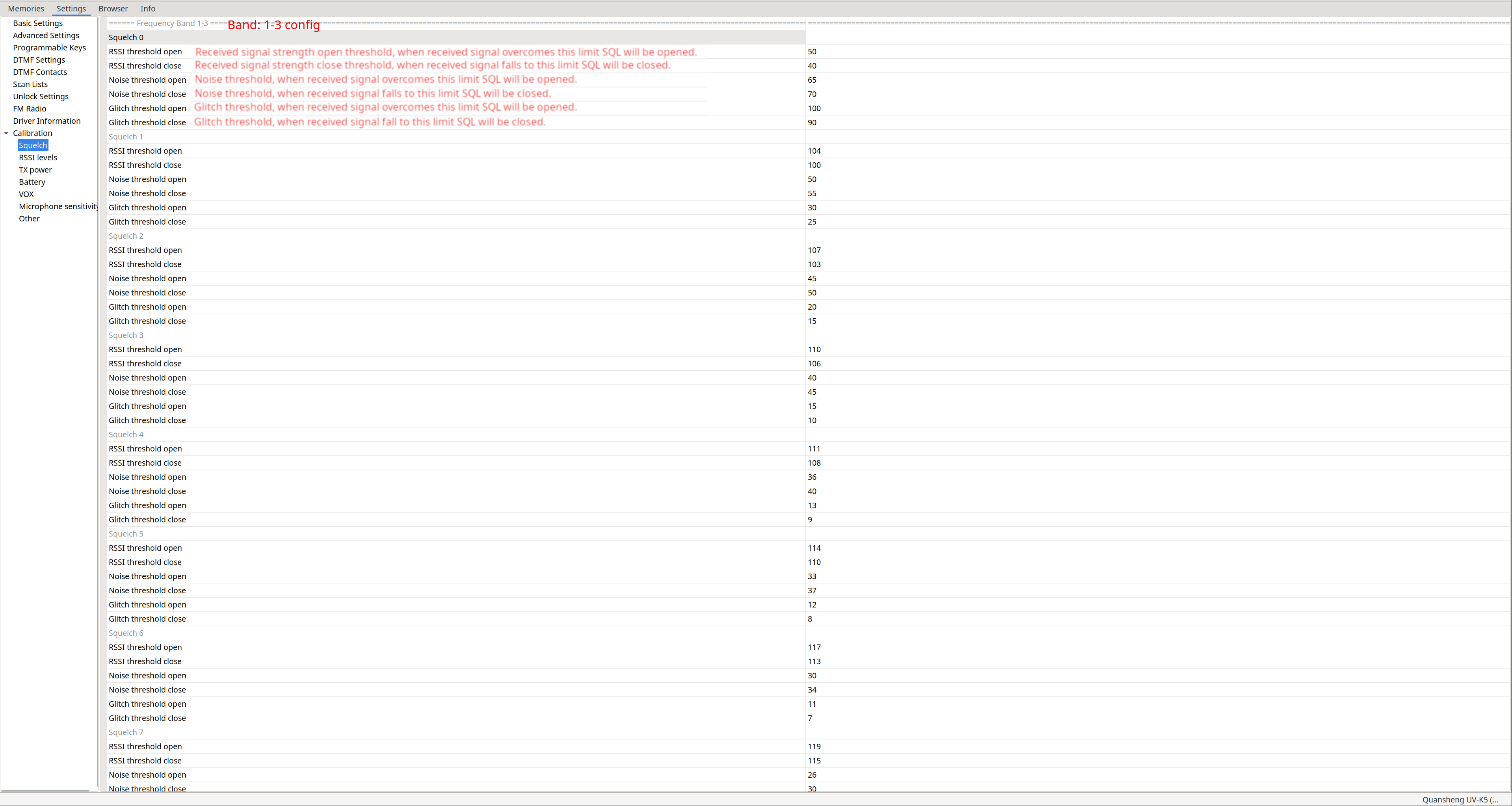
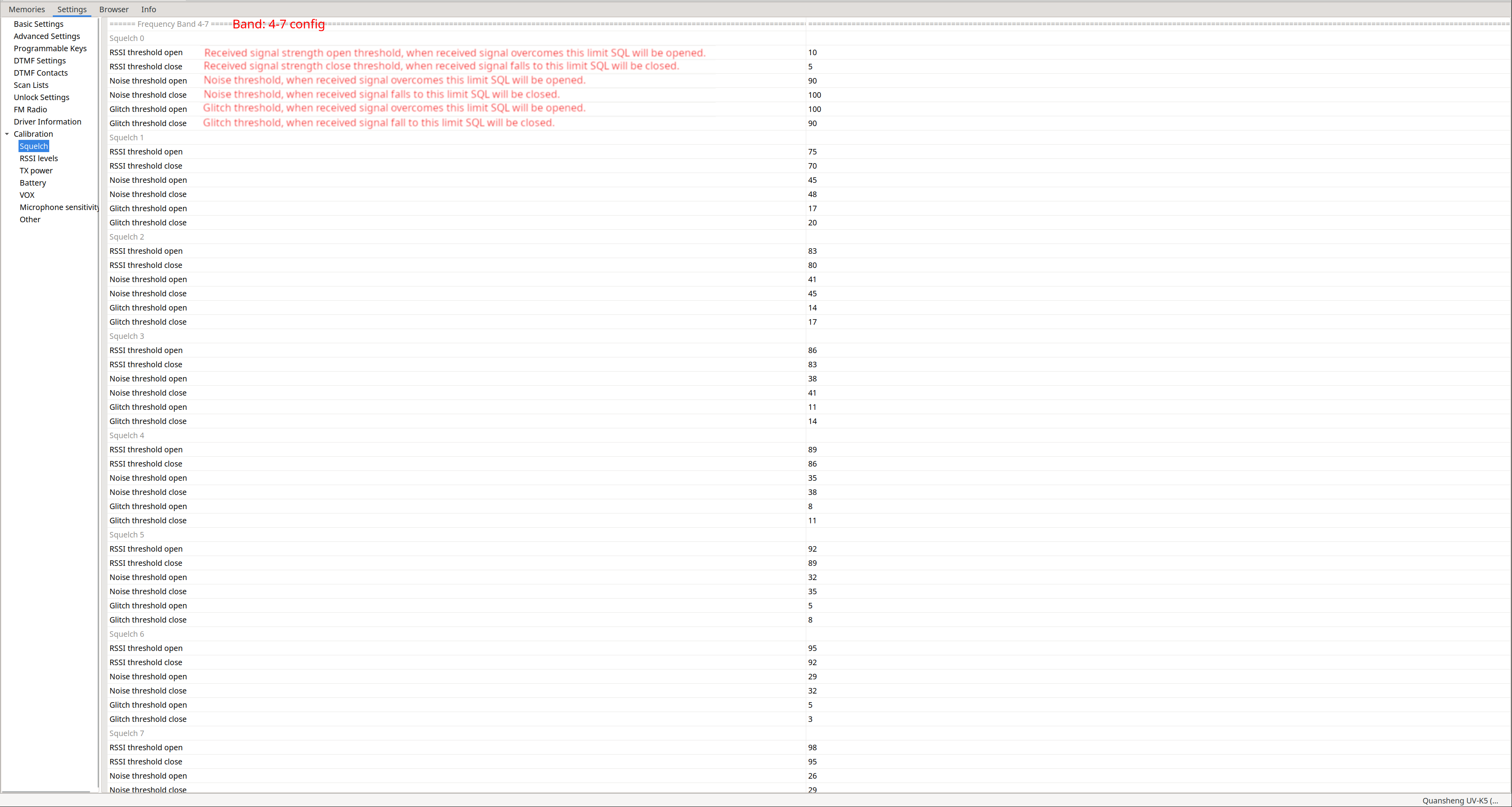
Calibration – Squelch: Allows adjusting the parameters for each squelch level (53). CHIRP only allows two configurations: one for the first three bands and another for the remaining four.
These values are read and multiplied by two by the firmware
.
| Bands: 1–3 | Bands: 4–7 |
|---|---|
|
|
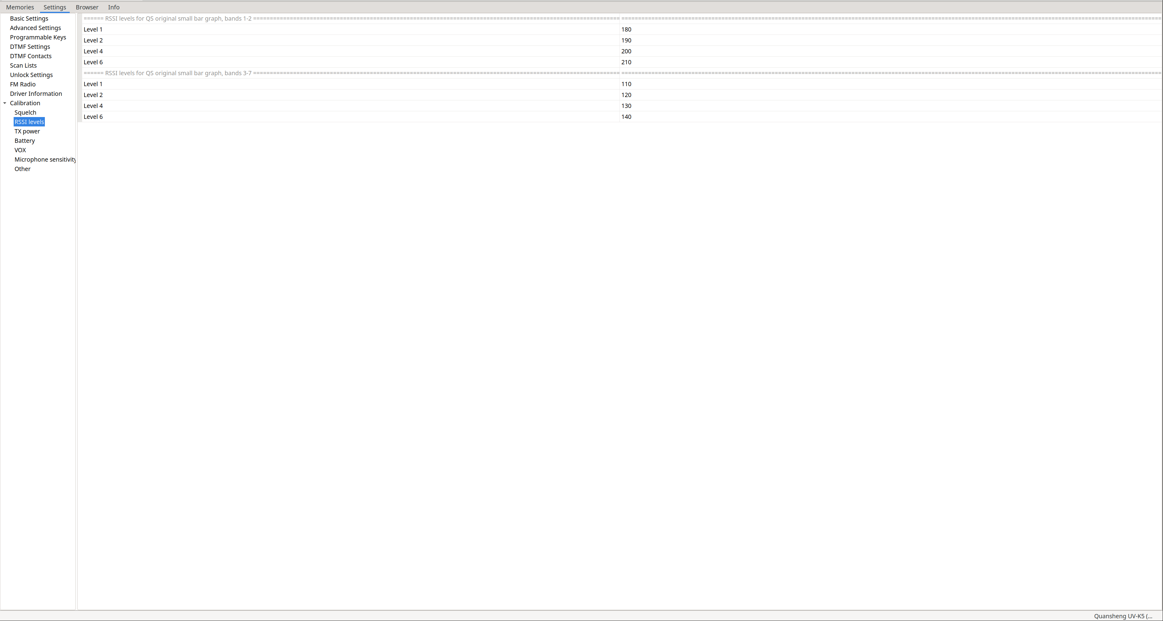
Calibration – RSSI levels: Allows defining signal quality thresholds to display different signal bars. Only two configurations are available: one for the first two bands and another for the remaining five.
Only used if the firmware was compiled with ENABLE_RSSI_BAR=0
.
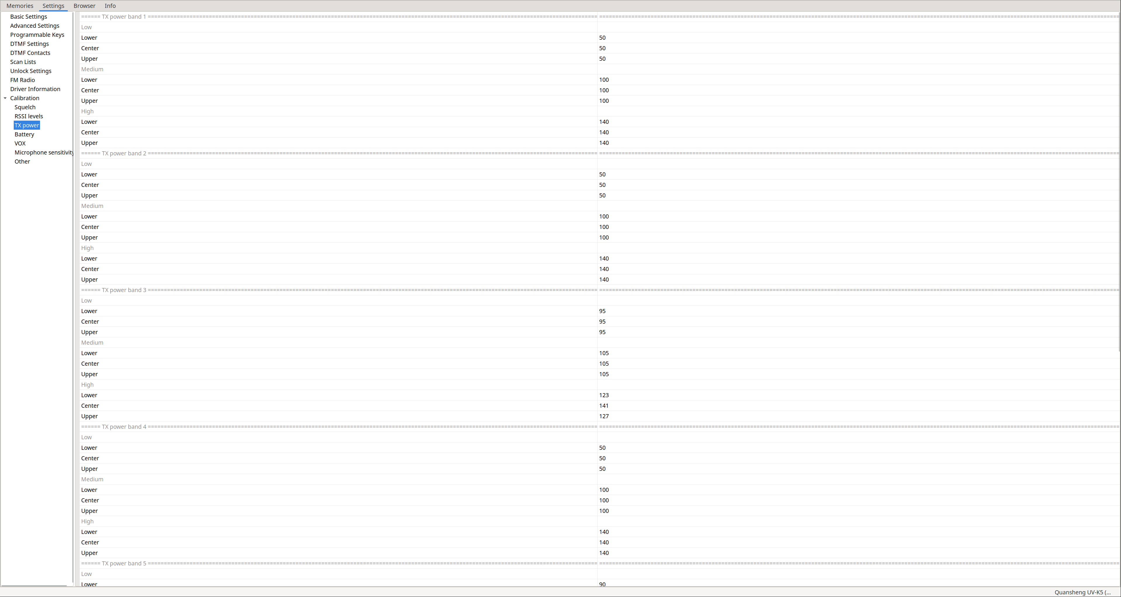
Calibration – TX power: Allows defining transmit power per band. If the firmware is compiled with ENABLE_REDUCE_LOW_MID_TX_POWER enabled, mid power is divided by 3 and low power by 5.
You can see Lower / Center / Upper values because bands are divided into X MHz regions. Depending on which region you are operating in, a different power value is applied. For example, in band F1 with the radio set to Low power, transmitting in the lower region uses Band 1 -> Low -> Lower, while in the upper region it uses Band 1 -> Low -> Upper.
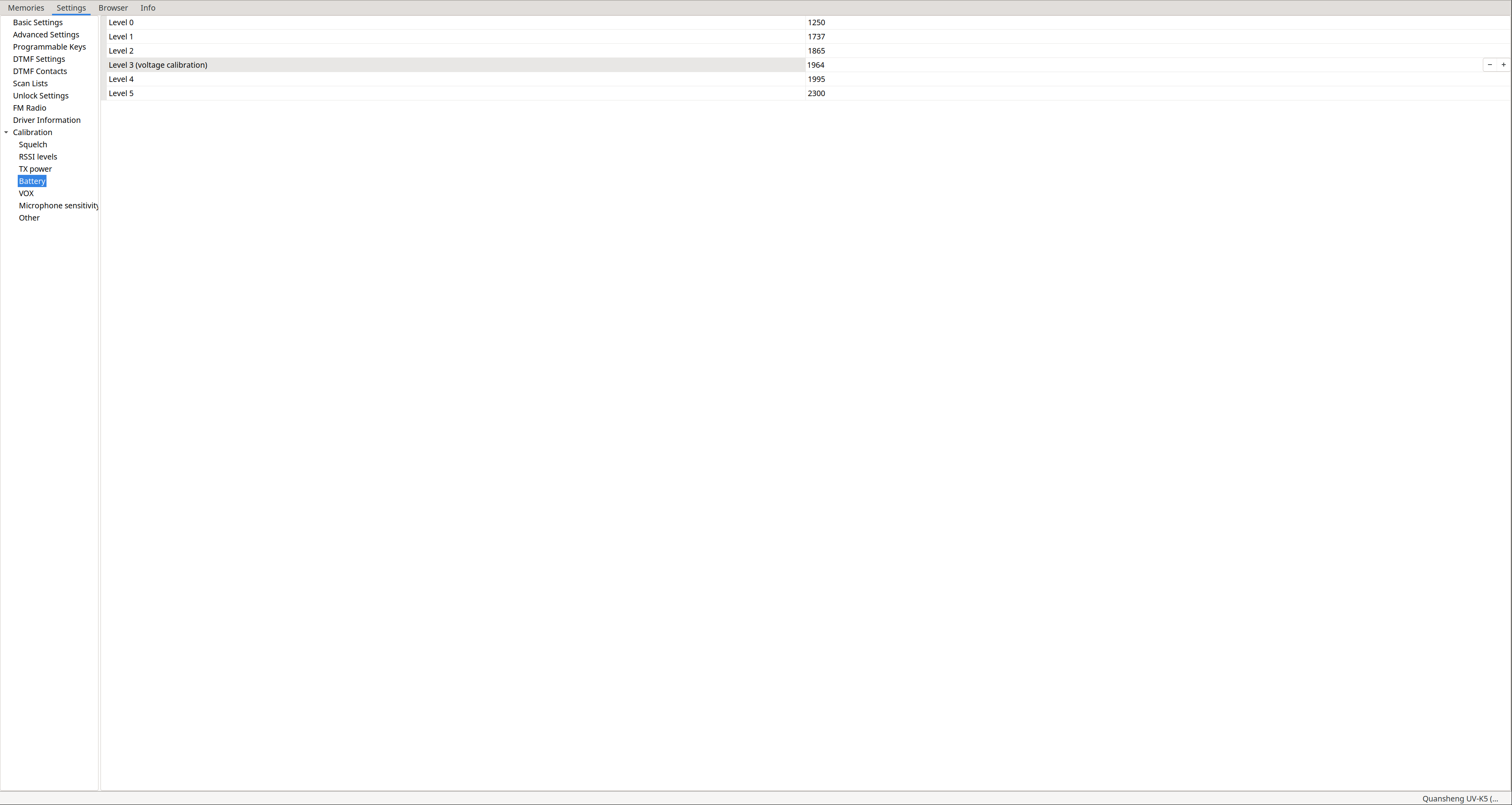
Calibration – Battery: The
NUNU documentation
does not mention details here, but I assume only level 3 is used, as in
EGZUMER
. This value can be configured using the
battery calibration procedure
.
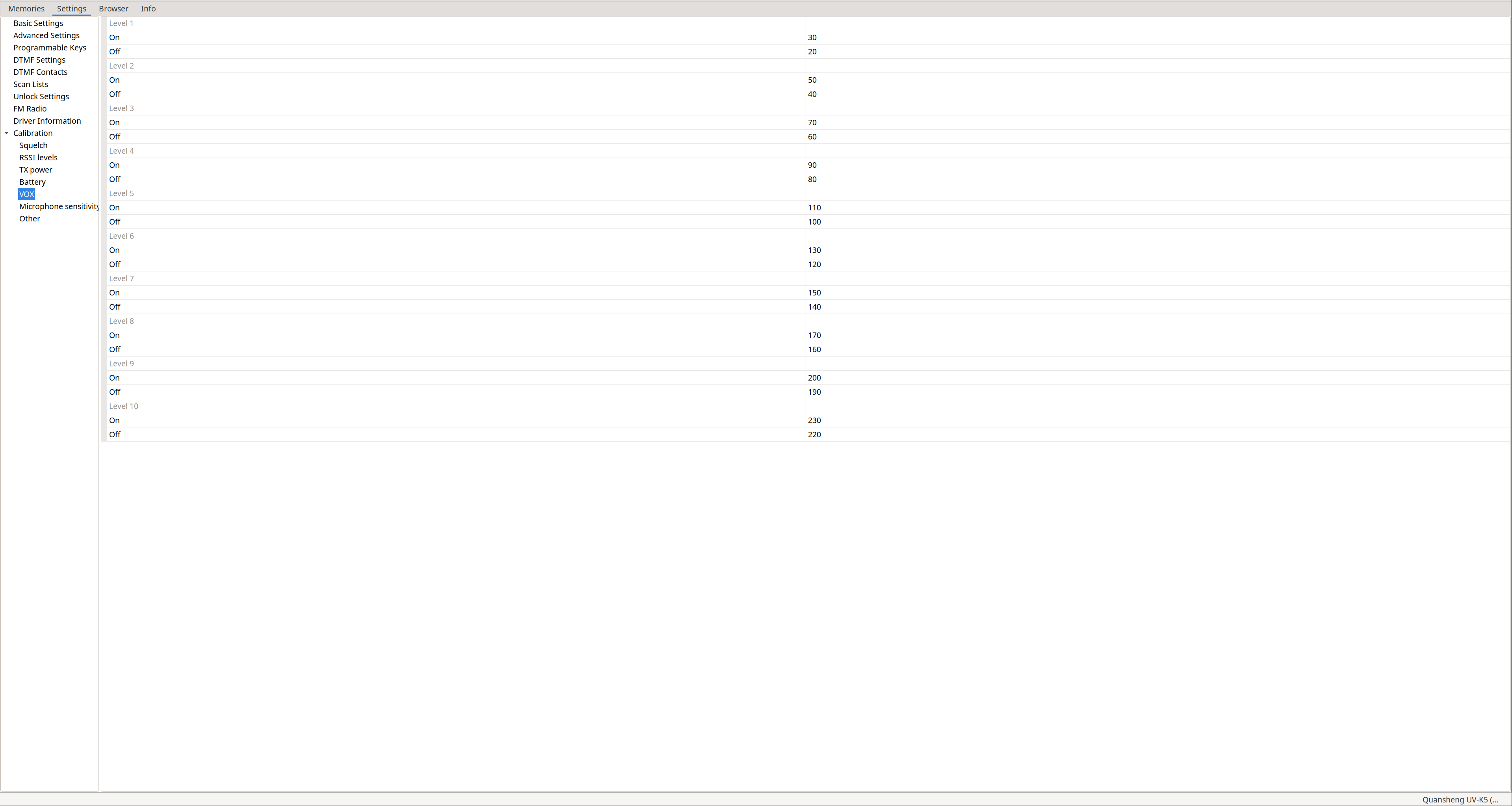
Calibration – VOX: Allows defining VOX activation thresholds for each level.
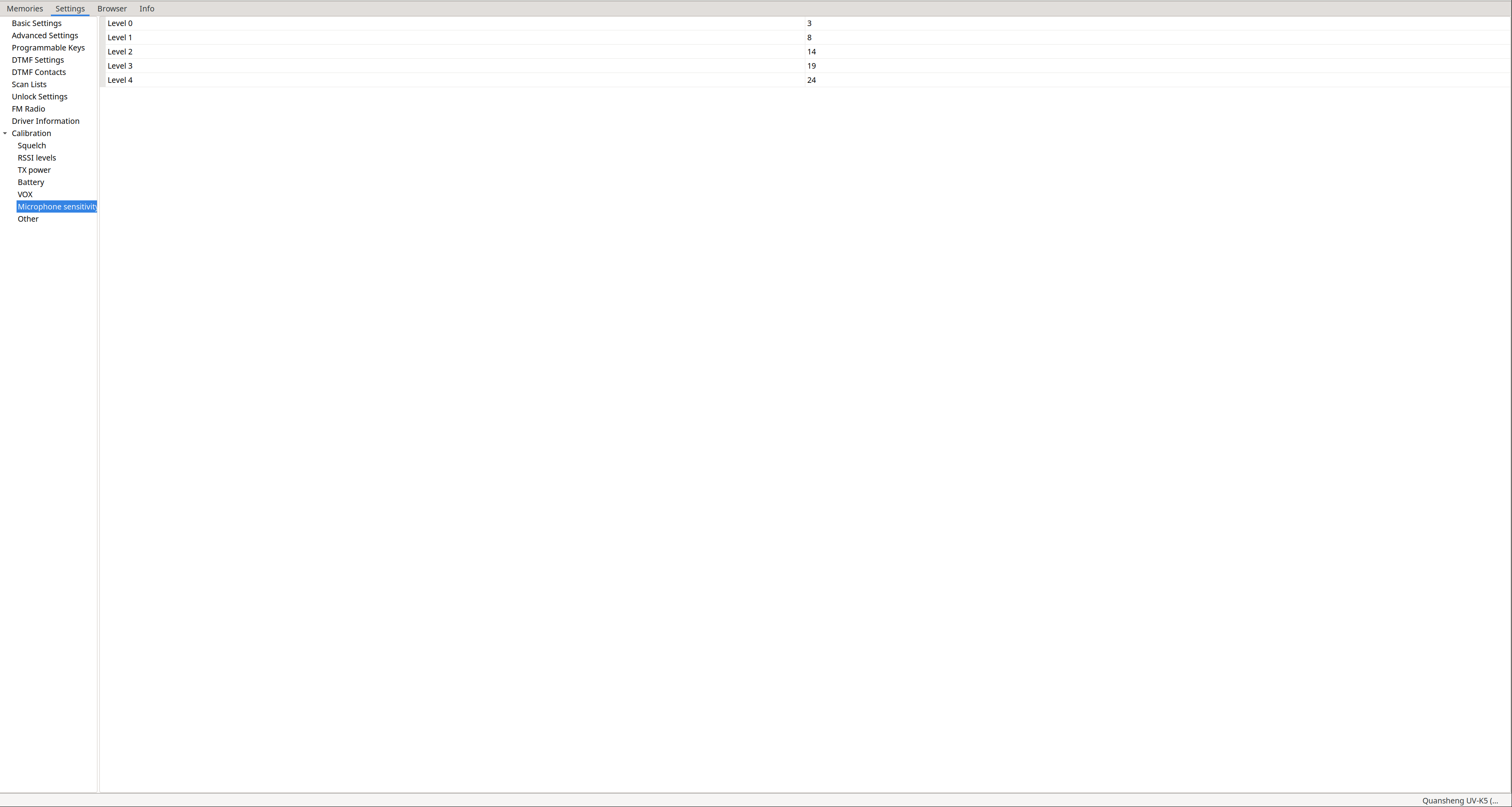
Calibration – Microphone sensitivity:
Not used
.
Calibration – Other: Crystal frequency configuration, volume gain, and DAC gain.
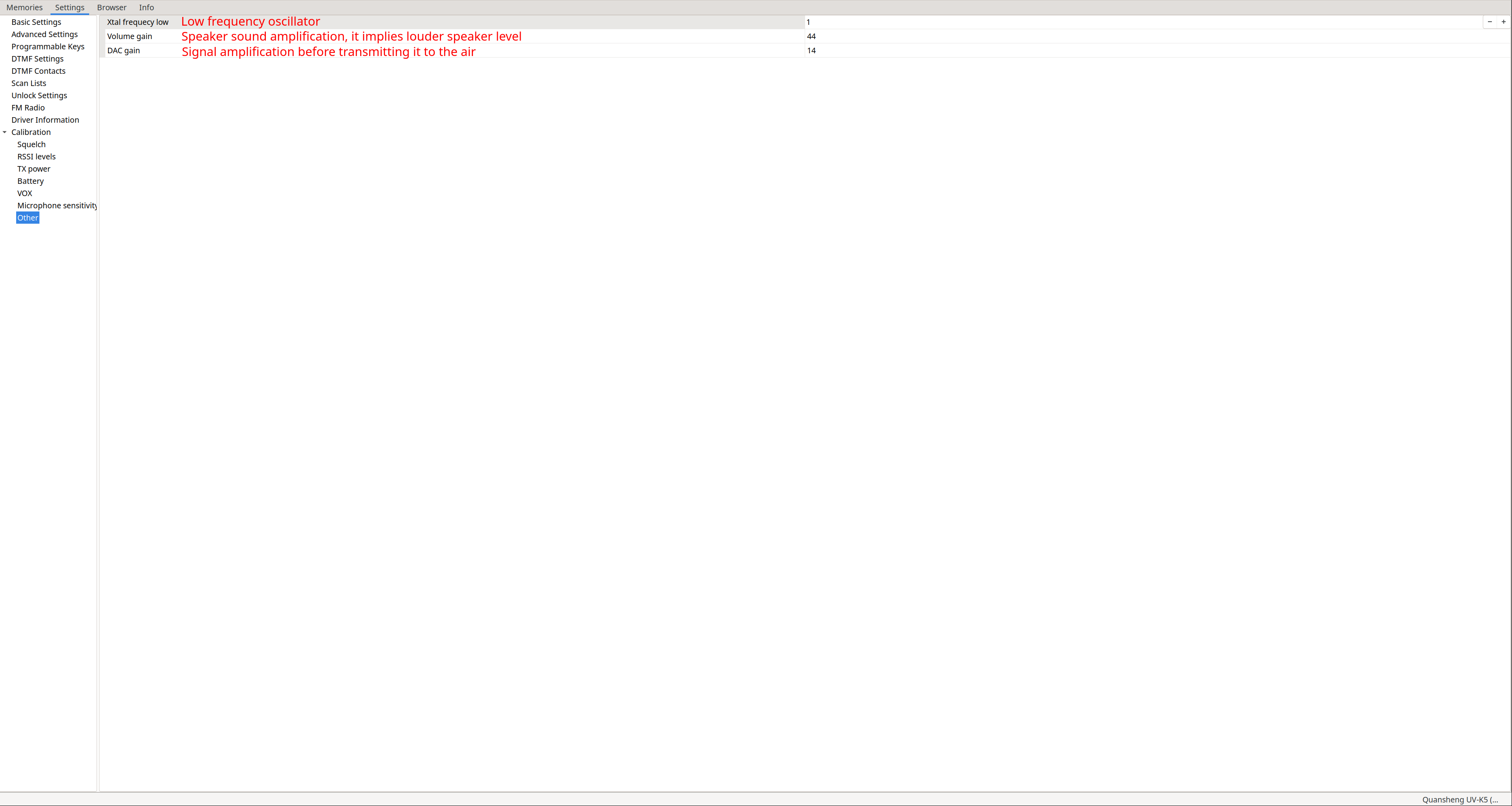
According to the datasheet of the radio chip , the walkie uses a 26 MHz crystal, and there is a variable capacitor used for crystal frequency calibration:
Cvar is an adjustable capacitor for frequency calibration.
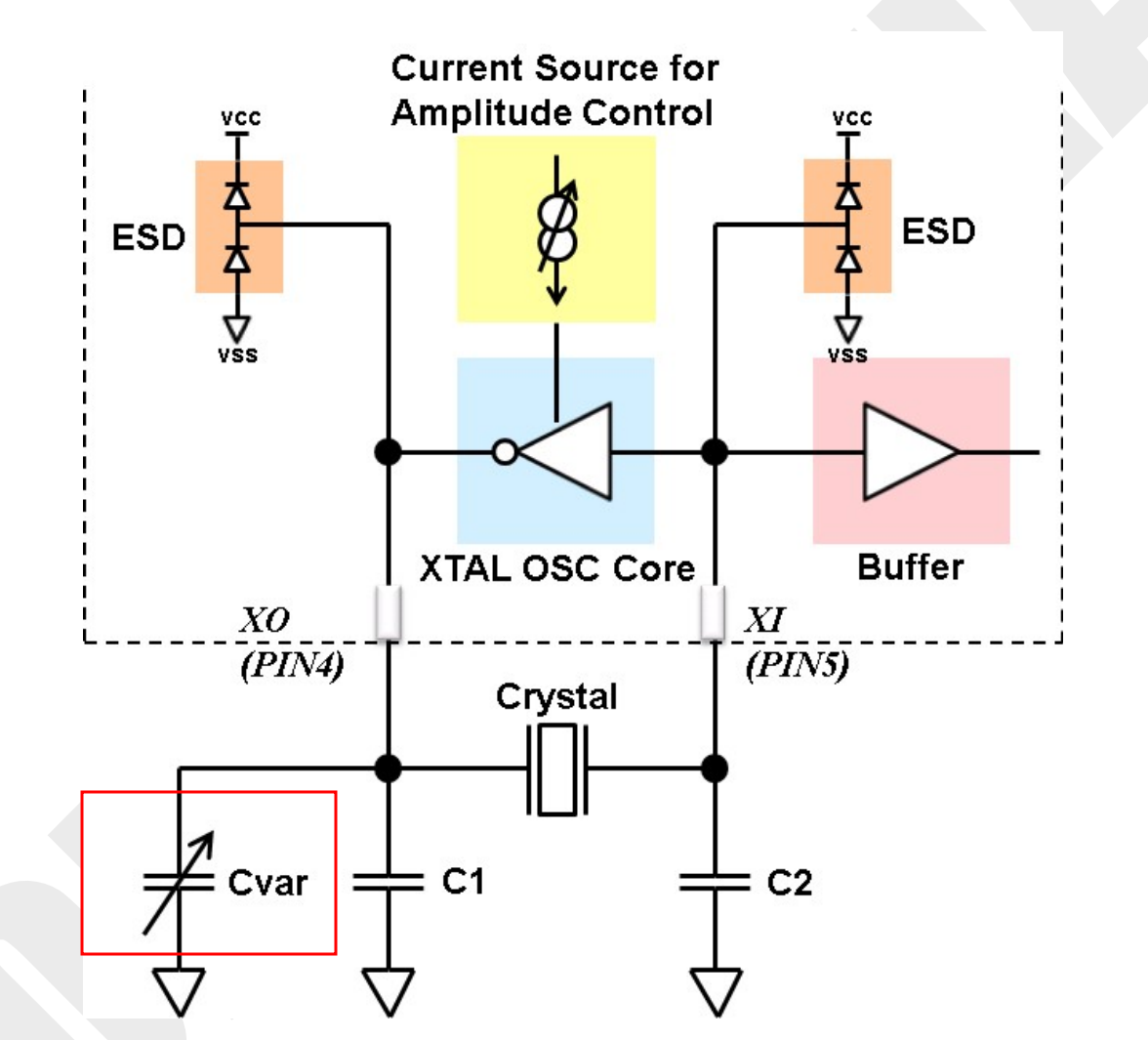
I assume that a 26 MHz crystal is considered low frequency, which is why Xtal frequency low defaults to a value of 1. I do not believe this parameter should be changed unless hardware modifications are made to the radio.
Messenger:
One of the most notable features of NUNU is its ability to send encrypted text messages between terminals. All functions related to the messenger can be found in the menu options:
-
EncKey(48): Displays the hash of the message encryption key. Useful to know if two walkies will be able to communicate, as the hash should match. Pressing
M(A)allows changing the key. -
MsgEnc(49): Enables or disables message encryption.
-
MsgRx(50): Enables message reception. With this option disabled, you can only send messages, not receive them.
-
MsgAck(51): Depends exclusively on the receiver. If enabled, an
ACKis sent for every message received, allowing the sender to know if the message was delivered. Any walkie withNUNUcan respond, so we know that someone received it, but not which walkie specifically. -
MsgMod(52): Modulation used to send messages. Depending on conditions, use one or the other:
- FSK 450 – for bad conditions
- FSK 700 – for medium conditions
- AFSK 1.2K – for good conditions
Think of the messenger like a chat group accessible to everyone, but only those with the correct key can read encrypted messages; unencrypted messages are readable by everyone.
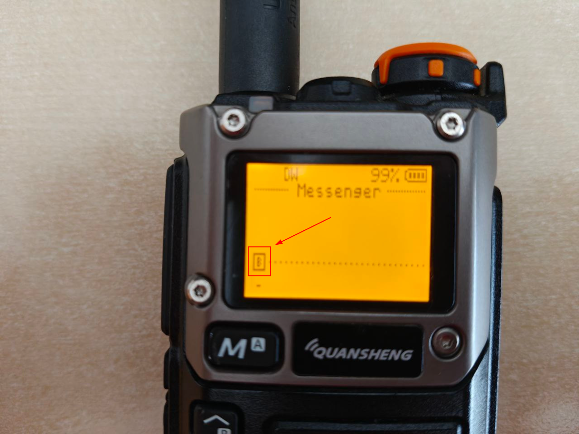
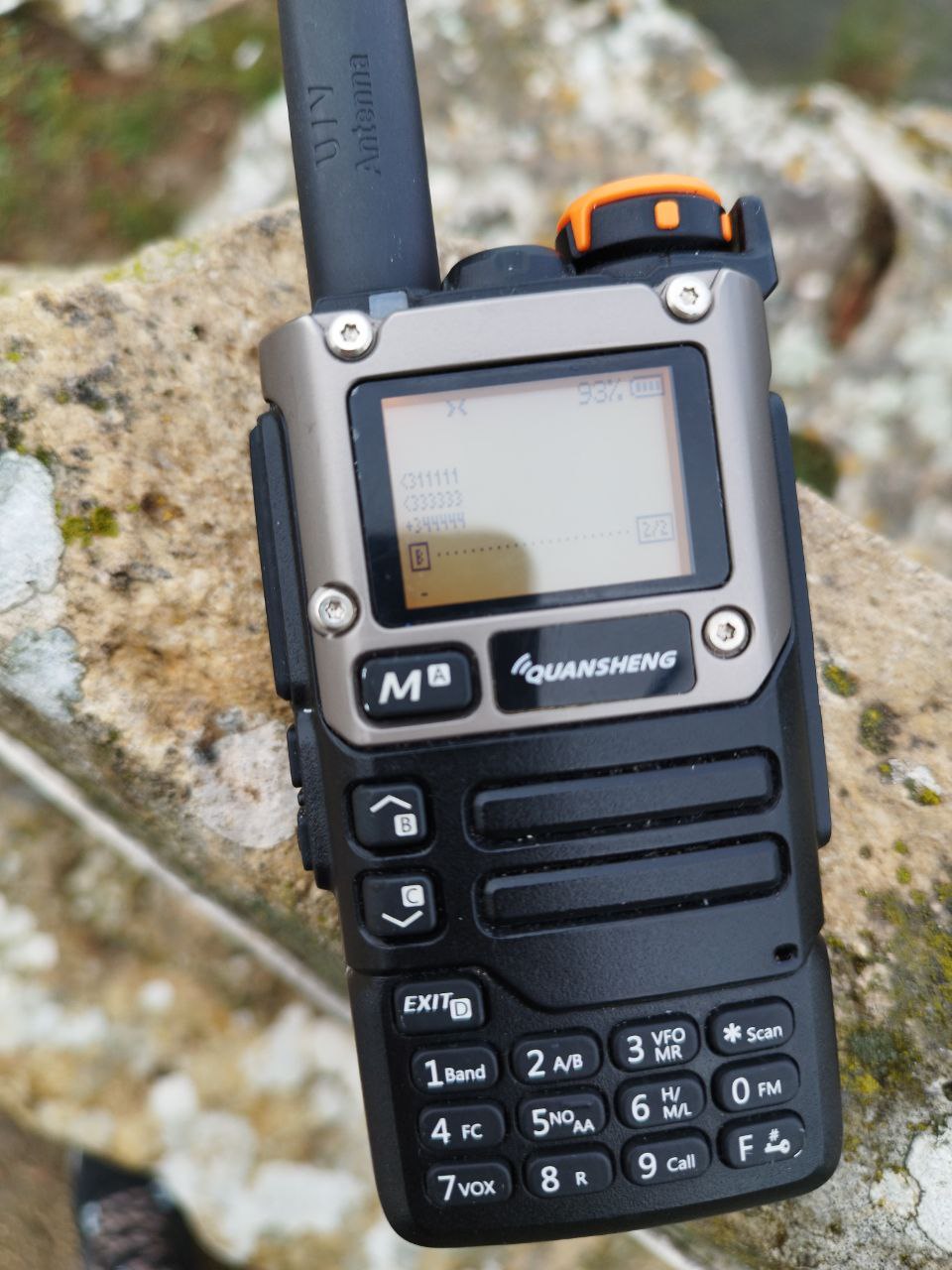
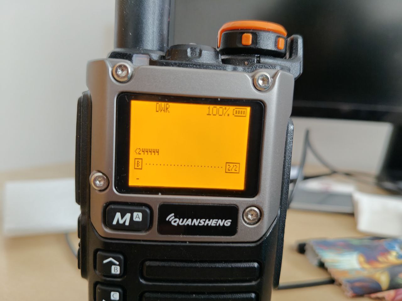
To access the messenger, press F+M(A), where the messaging interface appears (the B in red indicates the input mode: uppercase/lowercase/numeric). Using the buttons like in the ’90s, we can type the desired message.
|
|
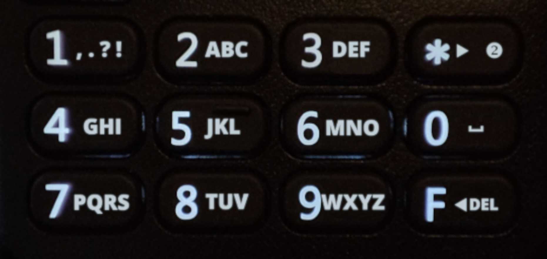
Some keys have specific functions:
| Key | Function |
|---|---|
1(Band) |
Punctuation marks. |
*(Scan) |
Switch input mode (uppercase, lowercase, numeric). |
0(Fm) |
Space. |
F(#) |
Delete. |
Up(B) |
Retrieve last sent message for editing. |
The message status is encoded with symbols as follows:
> Message sent, ACK not received.
+ Message sent, ACK received.
< Message received
Message encryption uses ChaCha20. More details are available on
the NUNU wiki
:
- Key derivation uses 256 bits generated from four 64-bit hashes of the password. Each hash uses a different 64-bit salt. The key is stored in
RAMuntil the radio is powered off. - The password resides in
EEPROM, so loading the same configuration on multiple walkies produces the same key, which is desirable when configuring multiple units. - Reading the password via the serial port (Kenwood-K1) can be prevented by setting a boot
PIN(Passwd(47)), preventing EEPROM access without the PIN. NUNUgenerates a hash of the password to quickly compare between two radios if they share the same encryption password, determining if communication is possible.
In the following video, we can see the messenger in action. Upon receiving a message, an alert sounds and a notification appears on screen. The left walkie has ACK enabled, while the right does not:
Encryption logic works as follows:
- If a message arrives encrypted and EncKey(48) does not match, we see gibberish.
- If a message arrives encrypted and EncKey(48) matches, it is decrypted automatically.
- If a message arrives in cleartext (sender: MsgEnc(49) Off), it is displayed directly.
This behavior can be seen in the videos below:
| Encrypted message: wrong EncKey(48) | Encrypted message: correct EncKey(48) | Cleartext message: wrong EncKey(48) |
|---|---|---|
Even with multiple walkies involved, it works without issues:
MESH Network:
NUNU can go a step further by forming a
MESH network of nodes
that forward messages between them. The only requirement is using the
BETA version of NUNU
or paying for
version >= 21.0
.
BETA release notes:
Here is an exclusive early beta release with the NUNU Protocol, that implements message hopping based on the Meshtastic principles.
Hopping is enabled as long as you have MsgAck enabled.
Use MsgMod AFSK 1.2K for this release.
Hop count will be shown next to received message.
This release also stores 10 messages in total, in 2 pages that can be scrolled with FN1 and FN2 buttons.
Key points:
- Medium access is checked by nodes before transmitting ( CSMA/CA : Carrier-Sense Multiple Access with Collision Avoidance). If the channel is busy, the node waits a random time (Contention Window) before retrying.
- Message
CRCis checked to prevent forwarding garbage. - Messages cannot only be sent; all nodes participate in forwarding in
MESHmode. - Even without the correct EncKey(48), nodes can forward messages but cannot read them.
- Maximum payload size is 30 bytes.
- Maximum
TTLis 7.
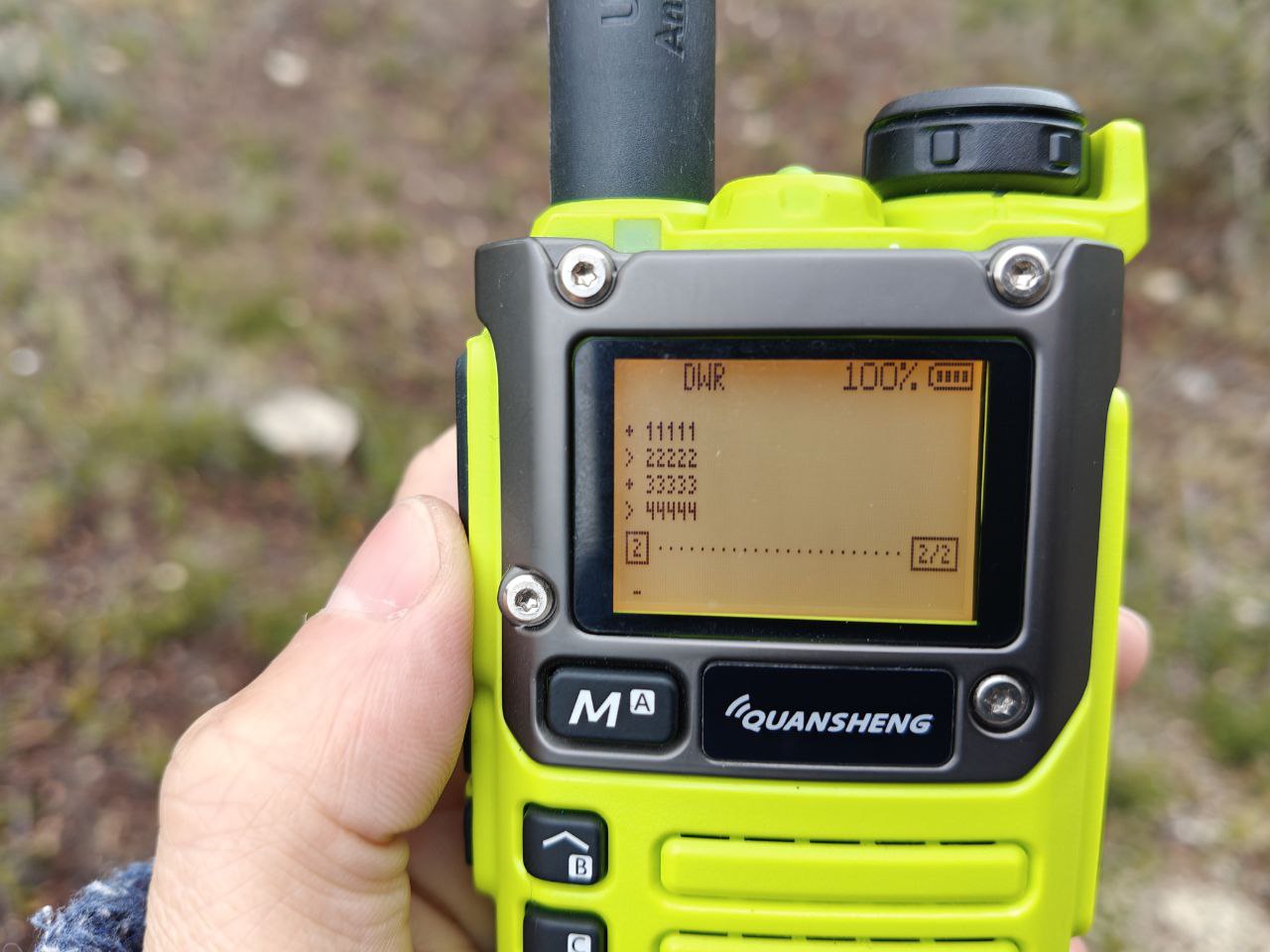
Message status symbols are similar but now include hop count:
- A space indicates the message originated on that walkie; hop count is unknown.
- A number indicates the number of nodes that have forwarded the message, shown on intermediate nodes and the final walkie.
ACK reception only indicates someone has received the message and is retransmitting it, not that it has reached the final destination.
Depending on the sender, repeater node, or final receiver, the encoded information appears as follows:
Sending walkie:
> Message sent, ACK not received.
+ Message sent, ACK received.
Repeater node:
<HopCount Message received and forwarded.
+HopCount Message received, forwarded, and ACK from forwarding received.
Final walkie:
<HopCount Message received.
In my tests, walkies were in 3 locations:
- Home - Puig: 4.7 km
- Puig - Portell de Catí: 23.36 km
- Home - Portell de Catí: 25.52 km
| Cacti | Puig | Home |
|---|---|---|
|
|
|
As seen, ACK only seems to work between the last pair of walkies in communication. The origin does not receive ACKs from intermediate or final nodes, only the intermediate node receives an ACK from the final one.
HopCount also seems inconsistent: the origin shows nothing, the intermediate shows correctly, and the final shows only 2.
Below is a video of the intermediate walkie forwarding a message: it first receives the message and forwards it, then receives the ACK from the final walkie: