EGZUMER is a truly appealing firmware for our beloved Quansheng K5(8)/K6(buy link) as it incorporates a large number of very interesting options. In this tutorial, we will learn how to flash it and how to use all its functionalities.
The EGZUMER firmware consists of the firmware by OneOfEleven along with the spectrum analyzer by fagci and a few more options. Its main characteristics are:
- AM fix: Improved reception quality in AM.
- The functions that required pressing the F(#) function key now can be enabled directly by holding down the respective key.
- Fast scanning.
- Editing channel names directly from the walkie-talkie itself.
- The ability to display both the channel name and the frequency.
- Shortcut for assigning channels to scan lists.
- We can switch between scan lists while scanning.
- Configuring the SideKeys directly from the walkie-talkie.
- Battery percentage in the status bar.
- Longer screen backlight times.
- Microphone input signal bar.
- RSSI S-meter: Received Signal Strength Indicator, antenna input signal bar.
- Greater number of steps.
- More sensitive squelch.
- Spectrum analyzer by fagci .
- USB modulation by fagci .
- Configurable backlight intensity.
- Battery recalibration, useful if battery level readings are erratic.
- Improved battery percentage calculation based on whether it’s 1600mAh or 2200mAh battery.
- The ability to assign a greater number of functions to the buttons.
- The ability to configure long-press of M(A) as a function.
- The ability to scan codes/tones from the reception configuration menu.
- Now, when a signal is detected during a scan, we can press M(A) to stay on that frequency or press Exit(D) to return to the frequency where we started the scan.
As a trade-off, some concessions had to be made since space is limited:
- AirCopy.
- NOAA support.
- Voice: There aren’t anoying menu voices anymore.
- Alarm: Alarm functionality deleted.
- TX1750 tone.
- Power on password.
If you’re new to the world of amateur radio, I recommend this previous article where the basics are explained.
The article consists of the following sections:
- Reflash
- Spectrum analyzer
- Scan frequency range function
- Battery calibration
- Functions
- Buttons and functions
- Frequency unlocking
- DTMF calls
- Frequency scanner
- Scrambling
- Remote kill
- CHIRP
- Bugs
Reflash:
Before we begin, we need to install Mono on Wine-Linux, and then proceed to make a backup of the configuration and calibration files as indicated in this previous article.
It is also recommended to save the current radio configuration, as this will be useful later to load the channels into the new firmware. We save it twice, in both CHIRP and CSV formats, because if there are issues loading, the CSV file can be edited in order to alter or remove the problematic fields.
To create the backup, just follow these steps in
CHIRP
:
Radio -> Download from radioFile -> Save As ...File -> Export to CSV ...
Additionally, we must stop using the CPS. Otherwise, it could corrupt the data used by EGZUMER.
Do not use Quansheng CPS it overwrites custom settings.
We download the
latest version of the firmware
:
The web flashing software recommended on the EGZUMER website does not detect the COM port in either FreeBSD or the Linux VM that I usually use for these purposes.
So, we download the official update software to run it through Wine in a Linux VM where
Mono
is installed.
We install the software from the official Quangsheng website following the steps outlined in
this article.
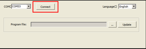
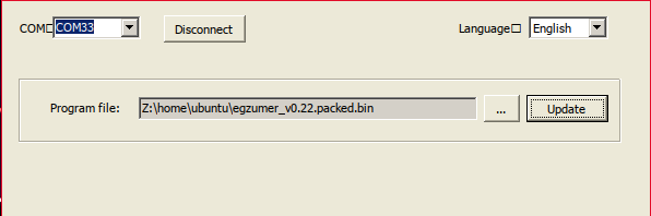
Then, we start the software:
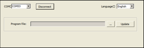
We press the PTT button and, without releasing it, turn on the walkie-talkie (the screen will go blank and the flashlight will turn on, indicating flash mode). Then, we connect the cable to the walkie-talkie, indicate the COM port 33, and connect:
|
|
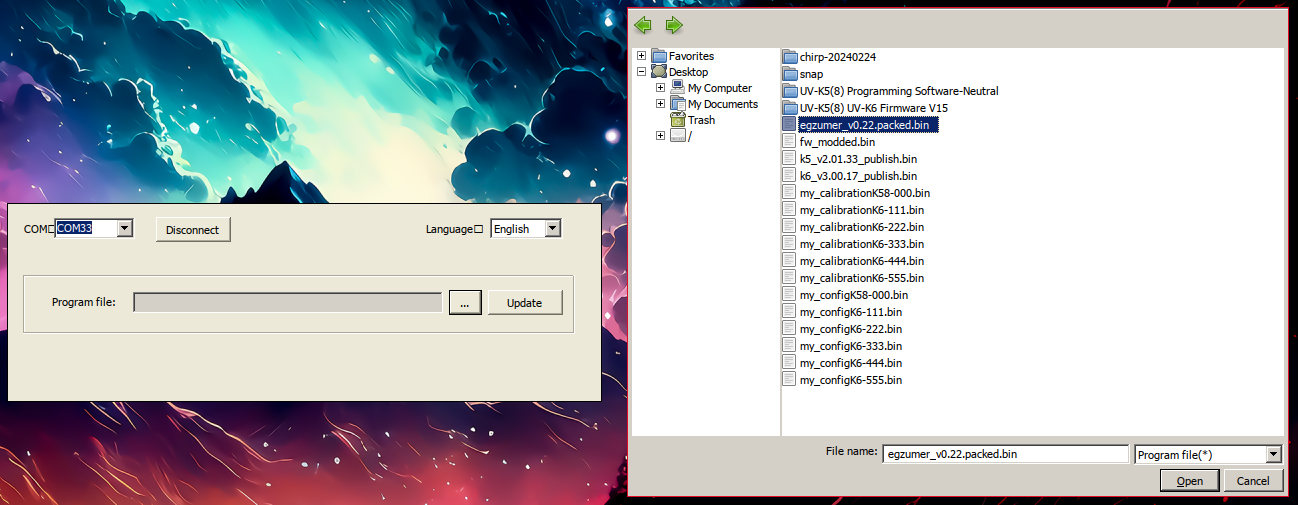
We click on the three dots and select the firmware file:
|
|
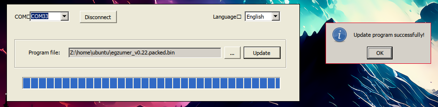
Now, we can proceed with the update by clicking on ‘Update’. Before performing any update, we will check the walkie-talkie’s battery level:
|
|
NOTE: If the Update button is not available, it’s because we haven’t started the walkie-talkie in flash mode.
For convenience, I have set up an alias to more easily run the software:
alias quanshengUpdate='WINEARCH=win32 WINEPREFIX=~/.local/share/wineprefixes/wineprefix32 wine ~/.local/share/wineprefixes/wineprefix32/drive_c/Program\ Files/Anonym/Portable\ Radio\ Update\ Tools/V1.1.12/Updater.exe'
Spectrum analyzer:
We can consult a quick guide on their GitHub or download the guide in PDF format. .
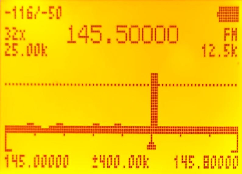
To access the spectrum analyzer, we must press: F+5(NOAA), the appearance should be similar to this:
For easier understanding, I’ll display the data in a table where each row represents a line of information on the display, and each parameter will be accompanied by an image from the previous example:
| First column of the display | Display | Second column of the display | Display | Third column of the display | Display |
|---|---|---|---|---|---|
| Zoom on the Y-axis: Maximum/Current value. 3(VFO/MR)/9(Call) |
 |
Battery | |||
| Number of channels to scan: How many channels (with the indicated bandwidth) it should monitor from the initial frequency. 4(FC) |
Frequency at which the signal of highest intensity has been detected within that frequency range. |  |
Modulation type. 0(FM) |
||
| Bandwidth of each channel. 1(Band)/7(VOX) |
 |
Bandwidth with which each channel is analyzed; depending on the signal emission, one bandwidth may be better than another. 6(H/M/L) |
 |
||
| Squelch line. *(Scan)/F(#) |
 |
Squelch line. | |
Squelch line. | |
| Spectrum: The triangle at the bottom shows the frequency of highest intensity, also displayed numerically at the top. |  |
Spectrum. | |
Spectrum. | |
| Initial frequency. 5(NOAA) |
 |
Scroll shift: How much we will shift the start of the frequency range when we press the Up(B)/Down(C) arrows. 2(A/B)/8(R) |
 |
Final frequency. |  |
NOTE: If the squelch is exceeded, it only shows in real time the status of that frequency (145.500 in the screenshot); the rest stop being monitored in real time.
- In the example, we can see that it’s monitoring 32 channels, each one with a bandwidth of 25kHz: 32 * 25 = 800kHz
- The initial frequency is 145.00000, so the final frequency is 145.00000 + 800 = 145.80000kHz.
- If we press the Up(B)/Down(C) arrows, we would shift through the spectrum by 400.00kHz. So, if we press the Up(B) arrow, the initial frequency would be 145.40000 and the final frequency would be 145.40000 + 800 = 146.20000kHz.
- The zoom on the Y-axis is adjusted to -50, and the channels are being analyzed using 12.5kHz bandwidth. Depending on the signal emission, one bandwidth may be better than another.
In addition to the functions shown above, there are some more which are accessed as follows:
| Button | Function |
|---|---|
| 5(NOAA) | It allows entering the initial frequency. We should press * to input ., and finally M(A) to accept. |
| SideKey1 | Exclude the current frequency from the scan. This way, we move to the second strongest frequency within the range. |
| SideKey2 | Enable/Disable backlighting. |
| PTT | Switches to detailed monitoring. |
Detailed monitoring: In order to access this menu, we will press PTT button.
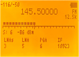
In the example, we can see a signal at level 6, equivalent to -86dBm, which just slightly exceeds the Squelch level.
In this menu, we can also make some adjustments:
| Button | Function |
|---|---|
| Up arrow(B) | Increases the frequency we are currently on. |
| Down arrow(C) | Decreases the frequency we are currently on. |
| 3(VFO/MR)/9(Call) | Zoom on the Y-axis: Maximum/Current value. Although in this visualization it’s not useful. |
| 5(NOAA) | Allows manual frequency input. Press * to input ., and finally M(A) to accept. |
| 6(H/M/L) | Bandwidth with which each channel is analyzed. Depending on the signal emission, one bandwidth may be better than another. |
| *(Scan)/F(#) | Squelch tunning. |
| 0(FM) | Changes the modulation type. |
| SideKey1 | Squelch openning. |
| SideKey2 | Enables/Disables backlighting. |
| Exit(D) | Return to the normal view of the spectrum analyzer. |
To access the parameters below, press M(A) and navigate using Up(B)/Down(C):
| Parameter | Function |
|---|---|
| LNAs | Low Noise Amplifier (Short): Amplifies signal with minimal added noise, details below(LNA: Low Noise Amplifier). |
| LNA | Low Noise Amplifier: Amplifies signal with minimal added noise, details below(LNA: Low Noise Amplifier). |
| PGA | Programmable Gain Amplifier: Amplifies signal post-LNA, after mixing and filtering, details below(IF: Image rejection architecture). |
| IF | According to the
datasheet
, IF is the combination of Filter+VGA(PGA)+ADC, but EGZUMER firmware refers only to the filter, details below(Incoming Signal Diagram). |
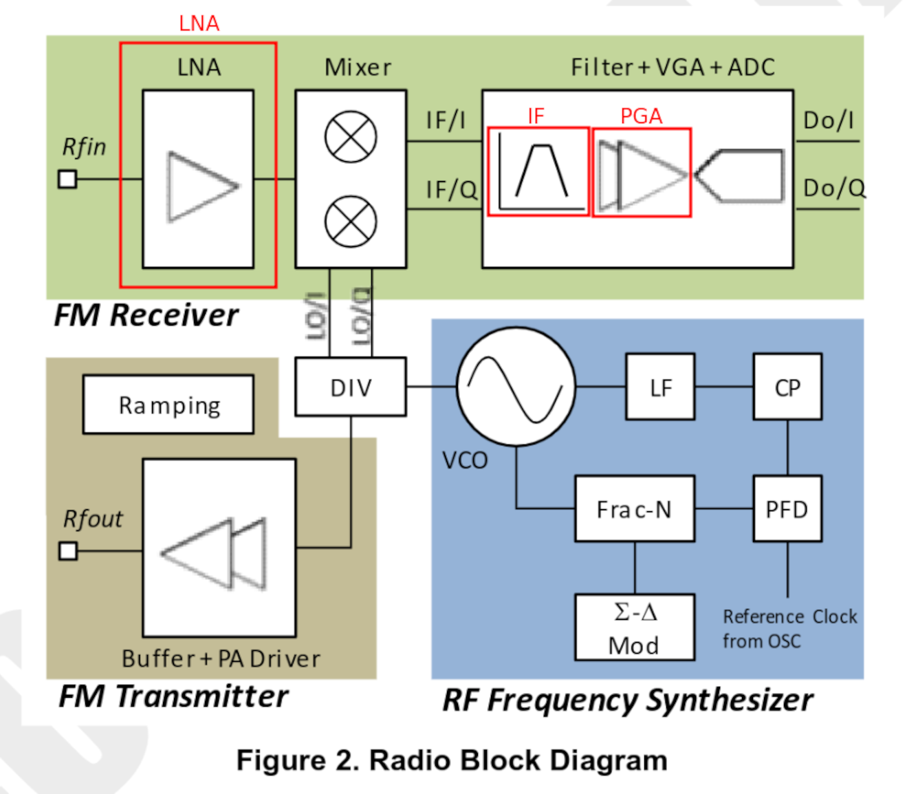
Below is the general signal processing diagram with elements adjustable in EGZUMER (LNA/IF/PGA).
Incoming Signal Diagram:
According to the
BK4819 datasheet
, the signal enters via the antenna, passes through the LNA (amplified), then through the MIXER, enters the IF where it is filtered, further amplified via VGA(PGA), and finally digitized.
Bear in mind the datasheet uses IF for the entire chain Filter+VGA(PGA)+ADC, while EGZUMER firmware separates them (IF = Filter, VGA = PGA).
These are labeled in red in the diagram.
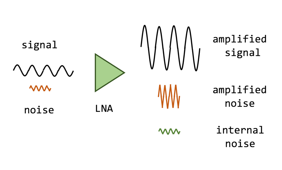
LNA: Low Noise Amplifier
Weak signals must be amplified while introducing the minimum possible noise. It’s important to consider that when amplifying a signal, we amplify the signal, the noise already present in the received signal and the noise introduced by the amplification circuitry itself.
The amplification is controlled through the RF module register: REG_10<9:8>/<7:5>
BK4819V3Registers_List
- LNA Gain Short is a 2-bit field, so we have 4 possible values:
| Binary value | Decimal value | Amplification |
|---|---|---|
| 00 | 0 | -19 dB |
| 01 | 1 | -16 dB |
| 10 | 2 | -11 dB |
| 11 | 3 | 0 dB |
- LNA Gain is a 3-bit field, so we have 8 possible values:
| Binary value | Decimal value | Amplification |
|---|---|---|
| 000 | 0 | -24 dB |
| 001 | 1 | -19 dB |
| 010 | 2 | -14 dB |
| 011 | 3 | -9 dB |
| 100 | 4 | -6 dB |
| 101 | 5 | -4 dB |
| 110 | 6 | -2 dB |
| 111 | 7 | 0 dB |
The total value is the sum of LNA Gain Short+LNA Gain, for example, if we configure:
- LNA Gain Short: 0 -> 00 -> -19 dB
- LNA Gain: 2 -> 010 -> -14 dB
The final amplification will be: -19-14 = -33dB
IF: Image rejection architecture
According to the
datasheet
the IF is composed of an LPF: band-pass filter, a VGA: variable gain amplifier, and an ADC: analog-to-digital converter.
But the IF value in the firmware seems to be adjusting only the bandwidth used by the LPF, which is controlled through the RF module register REG_3D<15:0>
BK4819V3Registers_List
IF Selection.
0=Zero IF;
0x2aab~=8.46kHz IF;
0x4924~=7.25kHz IF;
0x6800~=6.35kHz IF;
0x871c~=5.64kHz IF;
0xa666~=5.08kHz IF;
0xc5d1~=4.62kHz IF;
0xe555~=4.23kHz IF;
In the menu presented by EGZUMER, there is only a list of values, not frequencies, so I assume the frequency/value relationship is as follows:
0=Zero IF;            NOT A MENU OPTION
0x2aab~=8.46kHz IF;   1
0x4924~=7.25kHz IF;   10923
0x6800~=6.35kHz IF;   21845
0x871c~=5.64kHz IF;   32767
0xa666~=5.08kHz IF;   43689
0xc5d1~=4.62kHz IF;   54611
0xe555~=4.23kHz IF;   65533
PGA: Programmable Gain Amplifier
It’s a programmable signal amplifier, meaning it can be configured with different values. The amplification is controlled through the RF module register REG_10<2:0>
BK4819V3Registers_List
- PGA is a 3-bit value, so we have 8 possible values:
| Binary value | Decimal value | Amplification |
|---|---|---|
| 000 | 0 | -33 dB |
| 001 | 1 | -27 dB |
| 010 | 2 | -21 dB |
| 011 | 3 | -15 dB |
| 100 | 4 | -9 dB |
| 101 | 5 | -6 dB |
| 110 | 6 | -3 dB |
| 111 | 7 | 0 dB |
Scan frequency range function:
This firmware allows us to scan a range of frequencies without having to switch bands. We just need to use the first row of the display to indicate the start of the scan and the second row to indicate the end. This makes scanning much more convenient.
NOTE: It is also possible to enter a stored channel in one row and a frequency in the other row, performing the scan between the two rows.
Battery calibration:
To perform the configuration, we must access the extended menu.
SideKey1 + PTT + Power On
| Option | Menu-ID | Function |
|---|---|---|
| BatCal | 67 | It allows defining the current battery voltage to readjust the value displayed on the screen. |
| BatTyp | 68 | There are two types of batteries, and depending on the model, the discharge curve varies. Knowing which type of battery it has, it’s possible to calculate the percentage more accurately. |
| 1600mAh: 1600mAh version. | ||
| 2200mAh: 2200mAh version. |
The calibration can be done in two different ways:
| Manually: Charge the battery to 100% and adjust the BatCal(67) value until it displays 100% on the screen. | Multimer: Use a multimeter to check the actual charge. |
|---|---|
As we can see, upon returning to the menu, the value varies. It appears to be a firmware bug. I assume the final value is the one assigned from within the option itself, not the one displayed in the menu.
Functions:
To access the options, we must press the M(A) button and navigate using the arrows. We can also access options quickly if we know their ID. For example, if we know that the VOX option is 57, we can press M(A)+57.
In the following table are all the functions supported by EGZUMER, with additional features highlighted in bold/underlined if it’s a functionality not present in the stock firmware .
| Option | Menu-ID | Function |
|---|---|---|
| Step | 1 | How many kHz will advance or retreat when scanning or manually changing the frequency. |
| TxPwr | 2 | Transmit power, if high can affect adjacent channels: |
| LOW: 1w | ||
| MID: 3w | ||
| HIGH: 5w | ||
| RxDCS | 3 | Digital reception code: If we are on a frequency but don’t know the emission code our partner is using, we can press the F+*(Scan) key and the walkie will start scanning the DCS codes until it finds the correct one automatically. |
| RxCTCS | 4 | Analog reception subtone: If we are on a frequency but don’t know the emission tone our partner is using, we can press the F+*(Scan) key and the walkie will start scanning the CTCS tones until it finds the correct one automatically. |
| TxDCS | 5 | Digital transmission code . |
| TxCTCS | 6 | Analog transmission subtone . |
| T-ODir | 7 | Applies the offset in positive(+) or negative(-) used in repeaters . |
| T-Offs | 8 | Offset to apply in repeaters . |
| W/N | 9 | Bandwidth to use: |
| Wide: Short range, better sound quality. With Wide band, it’s advisable to use low power since it’s likely to affect adjacent channels. Lowering the power will at least limit the range of the disturbance. | ||
| Narrow( PMR446 ): Greater range, poorer sound quality. If our goal is range, we should also increase the power. In Narrow mode, it’s less likely to affect adjacent channels, and it consumes less battery than Wide mode. | ||
| Scramb | 10 | Encrypted Communication: Allows 1-10 types of scrambling. |
| BusyCL | 11 | Busy Channel Lock: If the channel is busy, it does not allow transmission. |
| Compnd | 12 | Compander (Compressor/Expander), it allows a signal with a wide dynamic range like the microphone to be transmitted through a channel with a narrower range like the walkie-talkie antenna, resulting in better audio quality by reducing noise and crosstalk , it must be enabled on both walkie-talkies: |
| TX: Enables the compander only for transmission signal. | ||
| RX: Enables the compander only for reception signal. | ||
| TX/RX: Enables the compander for both transmission and reception of signals. | ||
| OFF: Disables the use of the compander. | ||
| Demodu | 13 | Changes the modulation technique : |
| FM: By default. | ||
| AM: Only reception. | ||
| USB: Only reception. | ||
| ScAdd1 | 14 | Add channel to list1. This walkie-talkie allows you to create channel lists, so when you start scanning in channel mode it will only scan through this list, not all the stored channels. |
| ScAdd2 | 15 | This model allows for up to two customizable channel lists. This function is exactly the same as ScAdd1(14) but for the second list. |
| ChSave | 16 | Save channel. |
| ChDele | 17 | Delete channel. |
| ChName | 18 | It allows editing the channel name directly from the walkie. |
| SList | 19 | Enables a channel list for scanning. This functionality is also available while scanning; simply hold down *(Scan): |
| LIST1: Enable list1. | ||
| LIST2: Enable list2. | ||
| ALL: Enable all saved channels. | ||
| SList1 | 20 | We can view the contents of list 1. It seems that when priority channels are configured (Scan Lists section) in the list, it stops displaying the content correctly; it only shows the first non-priority channel on the list and the priority ones. However, scanning still functions correctly despite the inaccurate display. |
| SList2 | 21 | Exactly the same as SList1 but for SList2. |
| ScnRev | 22 | Scanning options: |
| CARRIER: When a signal is detected, it does not advance in scanning while the signal remains active. | ||
| STOP: When a signal is detected, scanning pauses for 5 seconds before continuing. | ||
| TIMEOUT: When a signal is detected, scanning stops. | ||
| F1Shrt | 23 | Button SKey1 configuration from the walkie-talkie itself: |
| FLASH LIGHT: Turn on the flashlight. | ||
| POWER: Change the transmission power. | ||
| MONITOR: Open the squelch(60). | ||
| SCAN: Start the scanning. | ||
| VOX: Enable the VOX(57). | ||
| FM RADIO: Starts FM radio. | ||
| LOCK KEYPAD: Lock the keyboard. | ||
| SWITCH VFO: Switch between channel A and channel B. | ||
| VFO/MR: Change the mode . | ||
| SWITCH DEMODUL VFO: Change the modulation type. | ||
| NONE: Disable the button. | ||
| F1Long | 24 | Same functionality as F1Shrt but for long button press. |
| F2Shrt | 25 | Button SKey2 configuration from the walkie-talkie itself. |
| F2Long | 26 | Same functionality as F2Shrt but for long button press. |
| MLong | 27 | Same functionality as F1Shrt but for long press of the M(A) button. |
| KeyLc | 28 | Keyboard auto-lock. |
| TxTOut | 29 | Maximum transmission limit, even with the PTT pressed, the transmission will be cut off after reaching X seconds. Useful for saving battery, preventing the walkie-talkie from overheating, or accidentally transmitting while in a backpack. |
| BatSav | 30 | Active/inactive time ratio, allows for battery saving. However, if it’s too aggressive, there might be signals that enter but the walkie-talkie won’t be aware as it was in one of the inactive slots, causing the loss of the first few seconds of an incoming communication, when PowerSave is enabled a PS will be displayed in the upper-left side of the screen: |
| Off: Always checking for an incoming signal. | ||
| 1:1: Half of the time is checked for an incoming signal. | ||
| 1:2: One out of every three time slots is checked for an incoming signal. | ||
| 1:3: One out of every four time slots is checked for an incoming signal. | ||
| 1:4: One out of every five time slots is checked for an incoming signal. | ||
| Mic | 31 | Microphone sensitivity. |
| MicBar | 32 | Displays a bar of the microphone audio level when transmitting. |
| ChDisp | 33 | Mode in which the information of a stored channel will be presented on the screen: |
| NAME: It will display the channel name. | ||
| CHANNEL NUMBER: It will display the channel number. | ||
| FREQ: It will display the channel frequency. | ||
| NAME + FREQ: It will display the channel name and frequency. | ||
| POnMsg | 34 | Power On Message: Power On Message: |
| FULL: Displays the entire screen in black, useful for detecting dead pixels. | ||
| MESSAGE: Message configured from CHIRP . | ||
| VOLTAGE: Voltage and battery charge. | ||
| NONE: No display, goes directly to the A/B channel screen. | ||
| BatTxt | 35 | How the battery charge should be displayed: |
| NONE: It will only appear filled with the typical bars. | ||
| VOLTAGE: The voltage appears next to the battery. | ||
| PERCENT: The percentage appears next to the battery. | ||
| BatLt | 36 | The time that the screen backlight will remain on: |
| OFF: It lowers the backlight to the minimum and disables it on the main screen. | ||
| ON: It never disables the backlight. | ||
| 5/10/20s 1/2/4m: Disables the backlight after the specified time. | ||
| BLMin | 37 | Minimum brightness of the screen when the backlight is disabled. |
| BLMax | 38 | Maximum brightness of the screen when the backlight is enabled. |
| BltTRX | 39 | Activation of the screen backlight when receiving or transmitting a signal: |
| OFF: It will not activate the backlight. | ||
| TX: It will activate the backlight only during transmission. | ||
| RX: It will activate the backlight only during reception. | ||
| TX/RX: It will activate the backlight both during transmission and reception. | ||
| Beep | 40 | Enable/disable the beep sound for each keystroke. |
| Roger | 41 | Sends a sound upon releasing the PTT to alert the other end that we have finished speaking, avoiding the need to say the typical “over”: |
| OFF: Does not send any sound. | ||
| ROGER: Beep. | ||
| MDC: Sound similar to a frog. | ||
| STE | 42 | Squelch Tail Elimination: If enabled, the walkie-talkie adds an inaudible tone at the end of transmission, which the receiver detects to prevent the annoying noise of releasing the PTT from being heard. |
| RP STE | 43 | RePeater - Squelch Tail Elimination: Some repeaters , upon receiving an incoming transmission, respond with a tone. This option prevents that tone from being heard through the speaker. |
| 1 Call | 44 | We assign the channel we want to switch to by pressing 9(Call) , it’s what used to be called “speed dial” in mobile phones. |
| ANI ID | 45 | DTMF Identifier used in DTMF calls , if we want to modify it, we must do it through the PC . |
| UPCode | 46 | DTMF code when pressing the PTT, the PTT ID(48) must be active in BOT or BOTH mode. |
| DWCode | 47 | DTMF code when releasing the PTT, the PTT ID(48) must be active in EOT or BOTH mode. |
| PTT ID | 48 | Configuration regarding whether to send the UPCODE(46), DWCODE(47), both, or none. This serves as an audible identifier for the receiver of the transmission. If they hear a tone they can recognize and associate with a walkie, they can mentally identify who is calling: |
| UP CODE: The UPCode(46) is sent when pressing the PTT. | ||
| DOWN CODE: The DWCode(47) is sent when releasing the PTT. | ||
| UP+DOWN CODE: The UPCode(46) is sent when pressing the PTT, and the DWCode(47) is sent when releasing the PTT. | ||
| APOLLO QUINDAR : A beep is sent when pressing the PTT, and another similar one is sent when releasing the PTT. | ||
| OFF: Disabled. | ||
| D ST | 49 | It allows you to listen to the DTMF tones that we are sending or receiving through the speaker. |
| D Resp | 50 | Automatic response to receiving a DTMF call : |
| DO NOTHING: If the receiving walkie receives its ANI ID(45), the audio will come out of the speaker. We could say it’s like an auto-answer feature on a phone. | ||
| RING: It behaves exactly like DO NOTHING, but additionally, it plays a ringing tone that will only stop when the receiver makes a transmission. | ||
| REPLY: It behaves exactly like DO NOTHING, but the receiving walkie also responds. This way, the transmitting walkie knows that the other side is active and can hear the audio. Testing the call from a stock firmware to an EGZUMER, the receiver responds but the transmitter doesn’t detect the response. Flashing both with EGZUMER firmware works without issues. | ||
| BOTH: It enables both RING and REPLY. It’s affected by the same issue as in REPLY. | ||
| D Hold | 51 | DTMF Hold: If emission stops on the channel during a DTMF call , the call will remain off-hook for the time configured in D Hold. |
| D Prel | 52 | DTMF Preload: Time between the start of an outgoing signal and the transmission of DTMF tones, higher values allow the receiving radio to detect the incoming signal and open the squelch (60) in time to not lose the DTMF codes. |
| D Decd | 53 | DTMF Decoder: Enables the detection of DTMF codes, we will only hear incoming audio if the sender transmits our ANI ID(45), necessary if we want to make or receive DTMF calls or use the remote kill function. |
| D List | 54 | DTMF contacts list, useful for identifying the walkie-talkies by name in a DTMF call . |
| D Live | 55 | Displays the received DTMF codes on the screen. |
| AM Fix | 56 | Activates the AM autogain function. |
| VOX | 57 | Voice detection, allowing transmission without pressing the PTT button; when the sound exceeds a certain threshold, the microphone will open, and the audio will be transmitted. |
| BatVol | 58 | Displays the voltage and the percentage of remaining charge in the battery. |
| RxMode | 59 | Reception mode of the channels: |
| MAIN ONLY: It only listens to and transmits on the main channel. | ||
| DUAL RX RESPOND: It listens on both channels simultaneously; if a signal comes through on the secondary channel, we can respond through it. | ||
| CROSS BAND: It listens on the secondary channel and transmits on the primary channel. | ||
| MAIN TX DUAL RX: It listens on both channels simultaneously, but always transmits on the primary channel. | ||
| Sql | 60 | Threshold from which incoming signal is detected, 0 means open, letting in all the noise. It’s worth noting that a low Squelch (SQL) setting will consume more battery as it’s constantly listening, not just when there’s an real signal. |
If we enter the extended menu, we will be able to see the extra configuration parameters, to do this, we start by pressing:
SideKey1 + PTT + Power On
| Option | Menu-ID | Function |
|---|---|---|
| F Lock | 61 | Assign the allowed bands for transmission. |
| Tx 200 | 62 | Enable the transmission in 200MHz F4. |
| Tx 350 | 63 | Enable the transmission in 350MHz F5. |
| Tx 500 | 64 | Enable the transmission in 500MHz F7. |
| 350 En | 65 | Enable the transmission in 350MHz F5. |
| ScraEN | 66 | Allow the posibility to enable the scrambling SCR(11), if this parameter is disabled from the extended menu, the parameter in the normal menu will not take effect. |
| BatCal | 67 | It allows defining the current battery voltage to readjust the value displayed on the screen. |
| BatTyp | 68 | There are two types of batteries , and depending on the model, the discharge curve varies. Knowing which type of battery it has, it’s possible to calculate the percentage more accurately. |
| 1600mAh: 1600mAh version. | ||
| 2200mAh: 2200mAh version. | ||
| Reset | 69 | Reset options: |
| VFO: Reset the configuration parameters. | ||
| ALL: Reset the configuration parameters and the saved channels. |
Buttons and functions:
| Button | Function |
|---|---|
| Wheel | Power and volume control. |
| M(A) | Main configuration menu. Configurable from PC or the walkie: Long press MLong(27). |
| Flechitas Arriba(B)/Abajo(C) | It allows us to navigate through the menu and change parameters. |
| Exit(D) | Exit the menu. |
| PTT | Push To Talk. |
| SideKey1 | Configurable from PC or walkie: Short press/Long press F1Shrt(23), F1Long(24). |
| SideKey2 | Configurable from PC or walkie: Short press/Long press F2Shrt(25), F2Long(26). |
| PTT+SideKey2 | Emits a tone of 1750Hz, necessary to access some repeaters. |
| Conector SP/MIC | Speaker/microphone and PC connector. |
| USB-C | USB-C charging port, only to be used in case of emergency. |
| *(Scan) | Allows making DTMF calls by dialing the ANI ID(45), SideKey1 can be used to delete. |
| 0(FM) | Enter the frequency in VFO mode or the channel number when operating in channel mode . |
| F(#) | Activate function mode. |
All keyboard buttons have a special function that is activated by pressing the F key or holding down the button marked with that function for a few seconds:
| Function | Functionality |
|---|---|
| F+0(FM)/LongPress 0(FM) | Activates the FM radio. |
| F+1(Band)/LongPress 1(Band): Change the band it operates on. | |
| F+3(VFO/MR)/LongPress 3(VFO/MR): Switch between VFO mode or the saved radio stations. | |
| F+*(Scan)/LongPress *(Scan): Scan and save the first 20 stations found. We can delete them by entering the MR mode and pressing M(A). | |
| ShortPress *(Scan): Scans until it finds a station, we can save it with M(A). If we press P.short *(Scan) again, we return to the previous VFO/MR mode. | |
| F+1(Band)/LongPress 1(Band) | Switches between available bands. |
| F+2(A/B)/LongPress 2(A/B) | Switches between one line of the display and the other. |
| F+3(VFO/MR)/LongPress 3(VFO/MR) | Switches between VFO mode and stored channels . |
| F+4(FC)/LongPress 4(FC) | Switches to frequency and code/subtone detection mode , we can press * if an incorrect one has been detected. |
| F+5(NOAA) | We access the spectrum analyzer . |
| LongPress 5(NOAA), modo VFO | Scan a frecuency range . |
| LongPress 5(NOAA), modo MR | It will alternate the channel membership between the two available lists. |
| F+6(H/M/L)/LongPress 6(H/M/L) | Changes the transmission signal power TxPwr(2). |
| F+7(VOX)/LongPress 7(VOX) | Enables the VOX(57). |
| F+8(R)/LongPress 8(R) | Enables the reverse mode . |
| F+9(Call)/LongPress 9(Call) | Switches to the channel configured in menu option 1 CALL(44). |
| F+*(Scan) | Find out the code/subtone when we are on a frequency or channel. |
| LongPress *(Scan) | If we are in
MR mode
it starts a scan on the currenst scanlist, if we press LongPress *(Scan) again, it alternates between the scan lists and *(all stored channels). If we are running a scan in VFO mode it starts a scan in the current band and frequency. If we press EXIT(D), the scan stops and returns to the original frequency, but if we press M(A), it stays on the last detected frequency. |
| LongPress F(#) | Lock the keypad. |
Frequency unlocking:
As the firmware’s own author comments , unlocking frequencies only allows for listening to them, not for transmitting. Additionally, transmitting outside the amateur radio bands can potentially damage the equipment:
This option won't give you ability to transmit in any other modulation than FM, this is a hardware limitation. Switching to AM or SSB only switches
AF audio output mode of a RF IC. It doesn't switch the whole IC into AM/SSB mode.
This is for listening only. This firmware is also built with additional lock that blocks TX when AM or SSB is on.
Let’s review the different bands supported by the walkie:
FM:            F1 50∽76 MHz
FM:            F2 108∽135.9975 MHz
FM:            F3 136∽173.9975 MHz
FM:            F4 174∽349.9975 MHz
FM:            F5 350∽399.9975 MHz
FM:            F6 400∽469.9975 MHz
FM:            F7 470∽599.9975 MHz
FM:            F7+ XXXXX-XXXXX MHz
AM:            F2 108∽135.9975 MHz
To access the extended menu for configuration, we need to enter the extended menu:
SideKey1 + PTT + Power On
From here, we can access the different options .
We must take into account some aspects:
- By default, we can listen on all bands, except for
F5, which is controlled by the350 Enoption. - The rest of the options control transmission on different bands.
F Lockenables typical ranges according to geographical region.- The special
DEFAULToption inF Lockenables additional ranges over 137-174, 400-470 through theTx 200,Tx 350,Tx 500options. Tx XXXenables additional bands beyond those indicated byF Lockbut only ifDEFAULThas been selected.
F Lock - Assign the allowed transmission bands.
    DEFAULT + (137-174, 400-470) - Allow transmission in F3 and F6 with the possibility of expanding via Tx 200, Tx 350, Tx 500.
    FCC HAM (144-148, 420-450)
    CE HAM (144-146, 430-440)
    GB HAM (144-148, 430-440)
    (137-174, 400-430)
    (137-174, 400-438)
    DISABLE ALL - Disable transmission on all frequencies.
    UNLOCK ALL - Enable transmission on all frequencies.

Tx 200 - Enable transmission on 200MHz F4.
Tx 350 - Enable transmission on 350MHz F5.
Tx 500 - Enable transmission on 500MHz F7.

350 En - Enables reception on 350MHz F5.
If we insist on unlocking transmission on all bands, we must follow a very
specific procedure
, access the extended menu and enable the option F-lock -> UNLOCK ALL 10 times in a row.
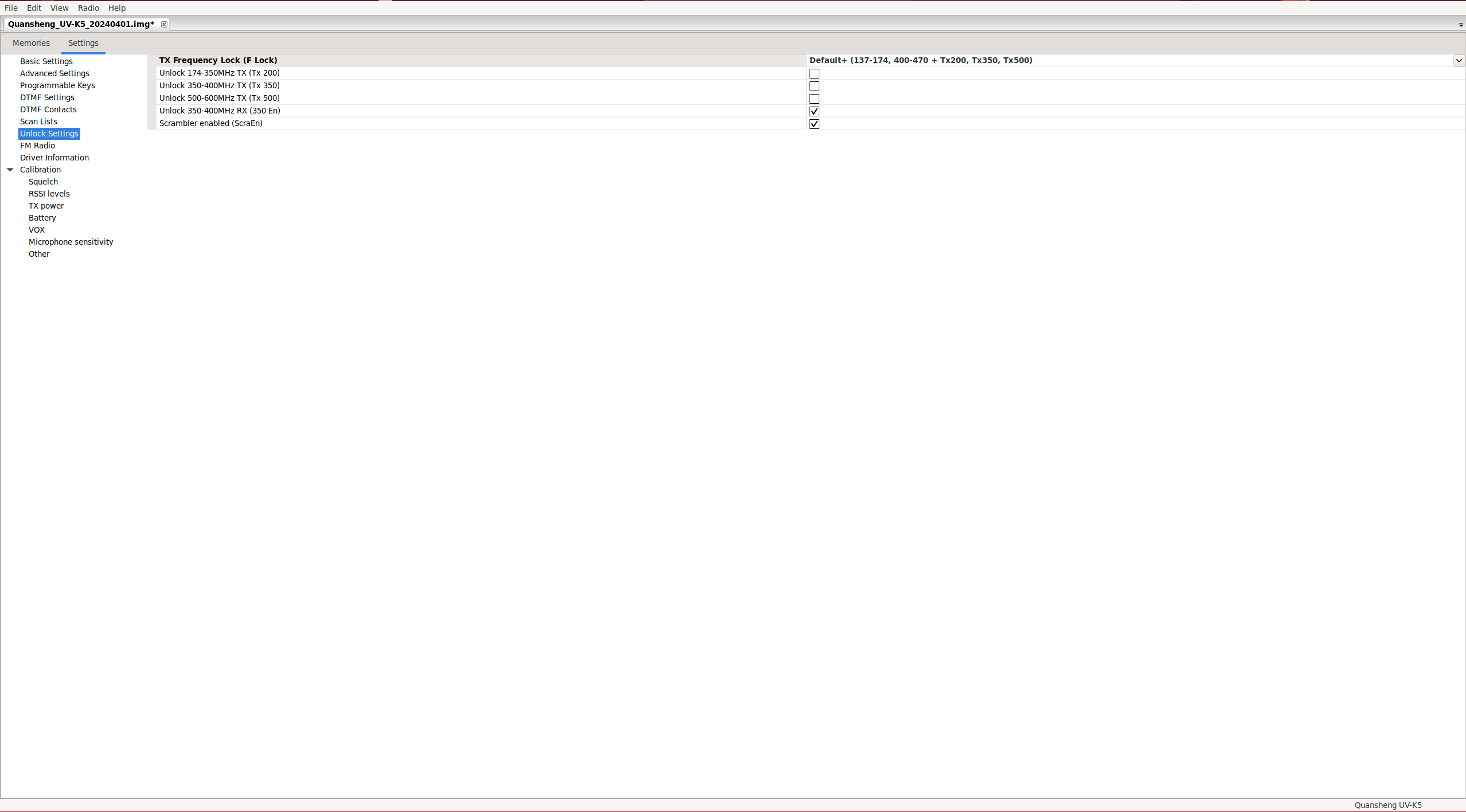
In my case, I’m going to enable only the typical amateur radio frequencies, the corresponding configuration options are:
F Lock: DEFAULT + (137-174, 400-470)
Tx 200 - OFF
Tx 350 - OFF
Tx 500 - OFF
350 En - ON
As you can see with this configuration, we can listen on all bands but only transmit on the amateur radio ones:
| TRX frequency bands configuration. | Unlocking all TRX frequencies. |
|---|---|
Keep in mind that even though unlocking the frequencies, they will always be FM; we can never transmit in AM. Also, the transmission power outside the amateur radio range will be very weak since the electronics were not designed for other ranges.
DTMF calls:
The basic idea is to have a set of walkie-talkies all on the same frequency and be able to call one of them or a group of them using DTMF codes. Each walkie-talkie must have a unique identifier called ANI ID(45) that can only be configured using PC software.
If we transmit on the channel without specifying the ANI ID(45), nobody who has D Decd(53) activated will hear us. The green light will illuminate since there is a radio signal coming in, but there won’t be any audio. However, if we specify an ANI ID(45) that matches a walkie-talkie, it will immediately hear the audio without having to “pick up”.
The configuration parameters D Resp(50) only apply to the receiving walkie-talkie:
- DO NOTHING: If the receiving walkie-talkie detects its own ANI ID(45), the audio will come out on the speaker. We could say it’s like a phone with automatic pick-up.
- RING: It behaves exactly like DO NOTHING, but additionally, it plays a ringing tone that will only stop when the receiver makes a transmission.
- REPLY: It behaves exactly like DO NOTHING, but additionally, the receiving walkie also responds. This way, the transmitting walkie knows that the other side is active and can hear the audio. Testing the call from a stock firmware to an EGZUMER, the receiver responds, but the transmitter does not detect the response. Flashing both with EGZUMER resolves the issue.
- BOTH: It enables both RING and REPLY. It is affected by the same issue as in REPLY.
If transmission stops on the channel, the call will remain auto-picked up for the time configured in D Hold(51). To cancel a call, we’ll have to press Exit(D) key. However, if we want to delete a character in DTMF dial mode, we should press SideKey1.
You can make calls in several ways:
- Manually: Holding
PTT,Receiver call ANI ID*Origin ANI ID. For example, if your ID is 666 and you want to call 100, it would be: 100 * 666. But in my tests, only the receiver of the call could receive the audio, even with REPLY activated. - Automatically: Pressing
*,Receiver call ANI IDandPTT. In this mode, our ANI ID is also sent automatically.
To call a group, you have to define the “Local code” character using the PC , assuming default value “#”, it works like this: calling 12# would reach users 120-129, while 1## would reach users 100-199, and ### would cover all possible users from 000 to 999. However, when calling a group, the REPLY function won’t work; the sender will talk blindly.
We must consider that this is still an open channel; anyone can receive and anyone can transmit on our frequency once a call is auto-accepted. That means if a colleague calls a walkie, it opens up communications. If at that moment a third party unrelated to the group transmits on that frequency, the two “friendly” walkies will hear the third party, and of course, this third party has always been able to listen to the audio of the “friendly” walkies.
I leave a demo video with DTMF contacts configured and D Resp(50) set to BOTH. We can appreciate the incompatibility between firmware versions:
- Stock firmware -> EGZUMER: The transmitter does not detect the response from the receiver (RSP), but the squelch is opened on both walkies.
- EGZUMER -> Stock firmware: Signal is received (green LED), the receiver does not respond, and only the transmitter opens the squelch.
- EGZUMER -> EGZUMER: It works without any issue.
| Stock firmware -> EGZUMER | EGZUMER -> Stock firmware | EGZUMER -> EGZUMER |
|---|---|---|
Depending on whether the walkie-talkie is the caller or receiver, the display lines will show specific information.:
| Caller | Receiver | |
|---|---|---|
| Upper line | Call status information. | Origin of the call. |
| Lower line | Destination of the call. | Destination of the call. |
Playing with the parameters D Hold(51)/D prel(52) doesn’t make any difference. I reported the issue. to the developer on the GitHub repository, but it seems there’s no solution since the stock firmware doesn’t use standard DTMF codes.
NOTE: If two devices are configured with the same ANI ID(45), both will respond to the call, allowing the initiator of the call and the two receivers to speak and listen.
Frequency scanner:
This walkie has a very interesting feature called Frequency Scanner: FC, which allows us to determine the frequency and the
tone/code
that another walkie-talkie is using, we just need to activate that function: F+4(FC)/LongPress 4(FC) and wait for the other walkie-talkie to emit a signal.
Finally, we can save the configuration in a memory slot as a channel by pressing M(A). This is very useful when working with people inexperienced in the world of radio who don’t even know what parameters they have configured.
Another functionality related to the FC is the Tone/Code scanner. If we know the frequency at which the counterpart is transmitting but we don’t know its tone/code , we can press: F+*(Scan), and it will automatically detect the tone/code . Finally, we can save the configuration in a memory slot as a channel by pressing M(A).
| Frequency scanner: F+4(FC)/LongPress 4(FC) | Tone/Code scanner: F+*(Scan) |
|---|---|
Scrambling
Conversations can be “encrypted” using scrambling Scramb(10), which is essentially a code used to encrypt the signal. The walkie that doesn’t have it configured will hear a distorted version of the audio.
We can see its effect on the following video:
We must remember that at least in Spain, encrypting any communication is illegal, so we must be very careful with this option. If we want to be extra cautious and ensure that it is never activated by mistake, we can access the extended menu and disable the possibility of activation by:
SideKey1 + PTT + Power On
ScraEn: OFF
As we can see, the SCR option appears in the menu, but when activated, it does nothing. We can see that the letters SCR do not appear on the right below the frequency:
Remote kill
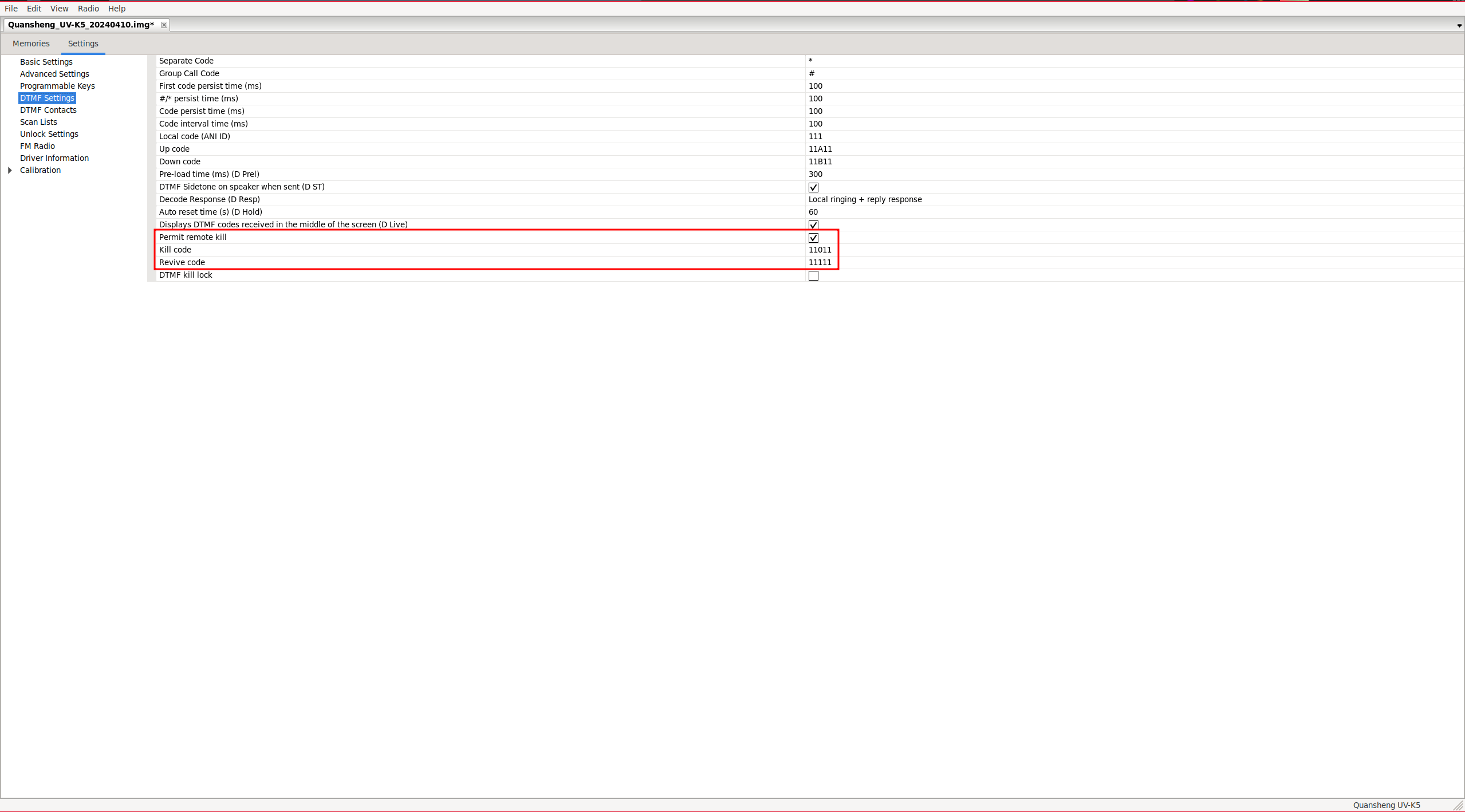
It’s possible to disable a walkie by sending it a sequence of DTMF tones (Kill code), known as remote kill. If the lost walkie is later found, it can be re-enabled using another sequence of DTMF tones (Revive code), but for this to work, the active channel must have the D Decd(53) option enabled.
We can see on the left the configuration of the walkie on the left in the video, and on the right, the configuration of the walkie on the right in the video.
| Left Walkie | Right Walkie |
|---|---|

|
|
To kill walkie 666, we must call: ANI ID * Kill code, in this case, 666 * 66066.
To revive it: ANI ID * Revive code, in this case, 666 * 66166.
As we can see, neither the Kill code nor the Revive code seem to do anything; it simply interprets it as a
DTMF call
, but in a somewhat peculiar way since only audio is heard on the receiver, and the origin of the call is identified as 660.
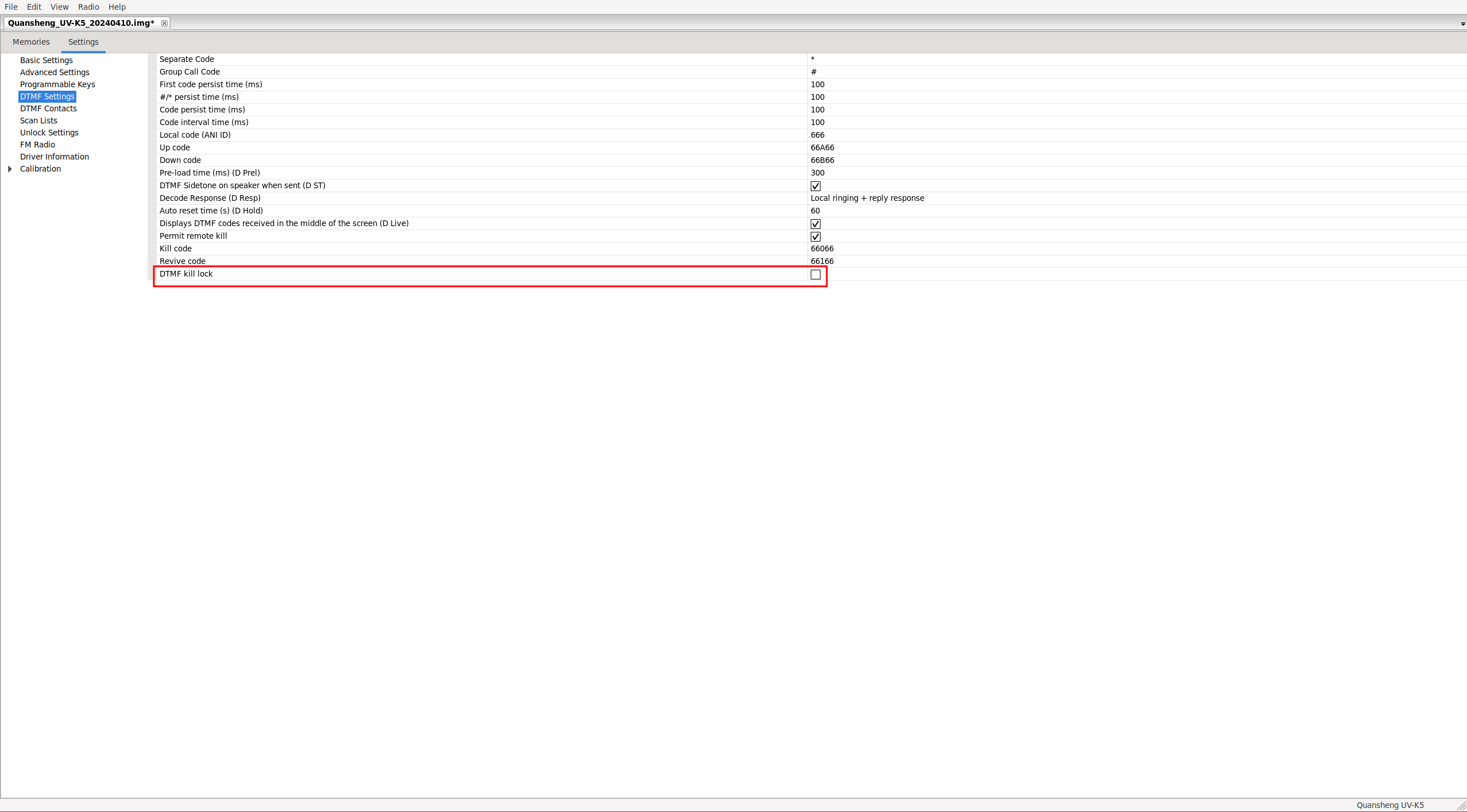
If we enable the DTMF kill lock option:
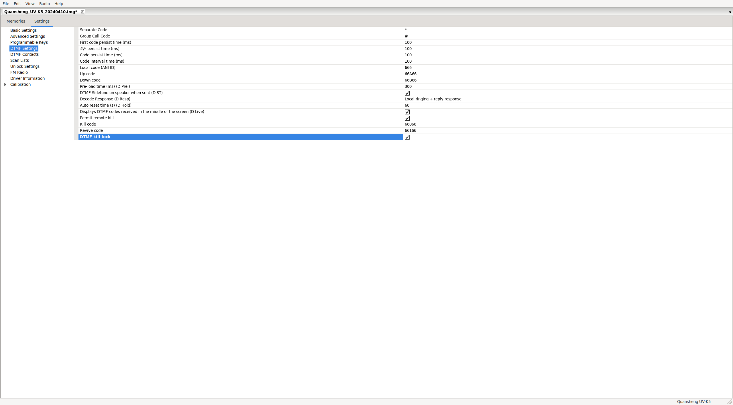
The walkie-talkie will be locked without needing to receive any code. It will only be unlocked upon receiving the Revive code or when reprogramming the radio from
CHIRP
with this option disabled.
NOTE: I suppose this could be useful if we want to limit someone’s use of the walkie from a certain day/time. We could give it to them locked, and when we consider it appropriate, unlock it for them to use. However, the problem is that it will remain permanently unlocked afterwards.
Once the Revive code is received, if we read the data from
CHIRP
, we will see that the option has been disabled.
I have opened an issue , but it seems that the mantainer is not so interested in resolving it.
CHIRP:
CHIRP is a widely used configuration software that supports a large number of devices
Previously, it was necessary to download the
driver for CHIRP
to interpret the new data structure of the EPROM used by EGZUMER.
But in the latest versions of CHIRP, it already includes it.
pip install chirp-20240401-py3-none-any.whl
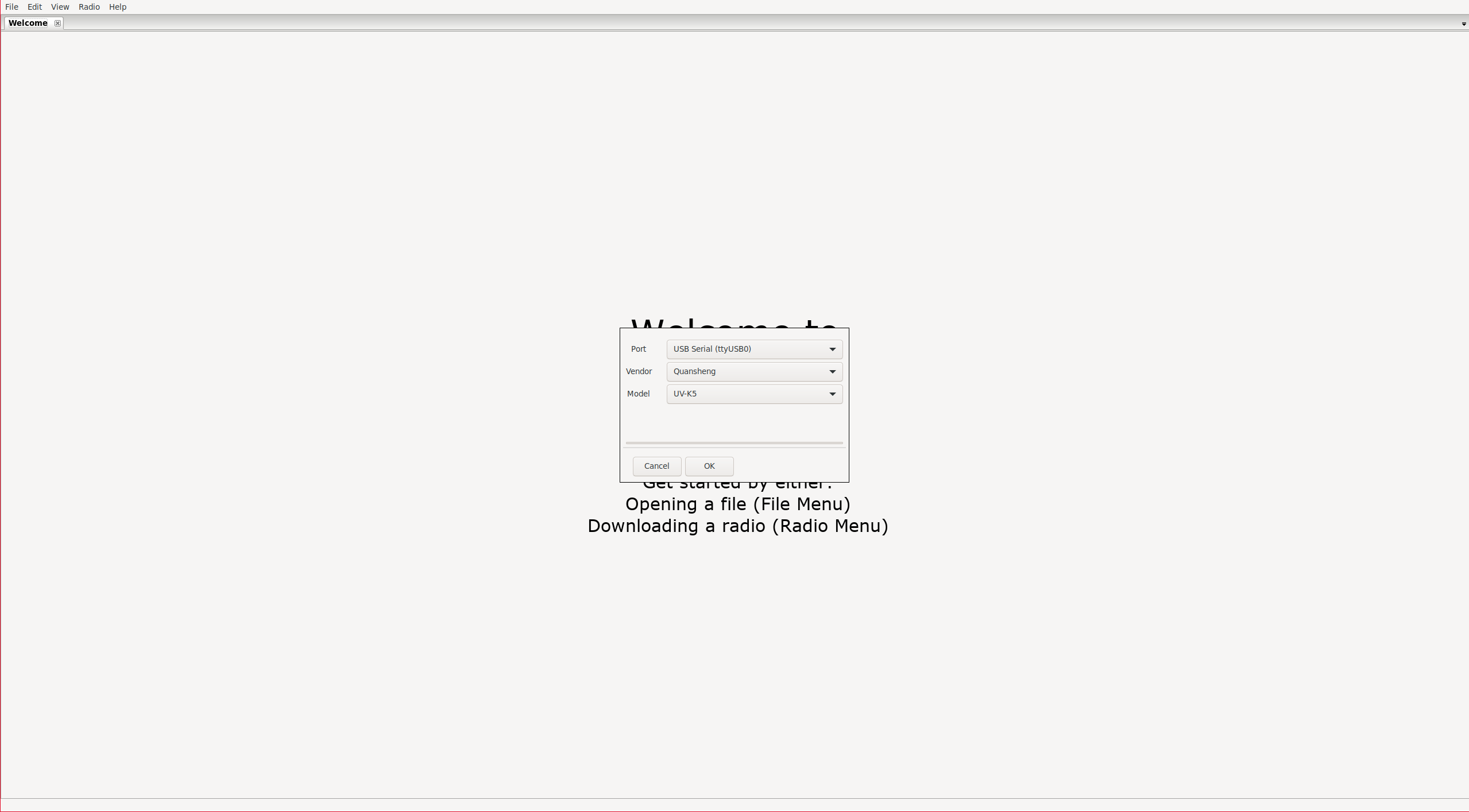
Let’s start the software:
NOTE: CHIRP is a rather cumbersome software. For example, if we select a value from a dropdown but do not move the focus away from the parameter, the value will NOT be applied. This means that if we upload the configuration to the radio, the change will not have been applied.
Connect with the radio:
Radio -> Download from radio

|
|
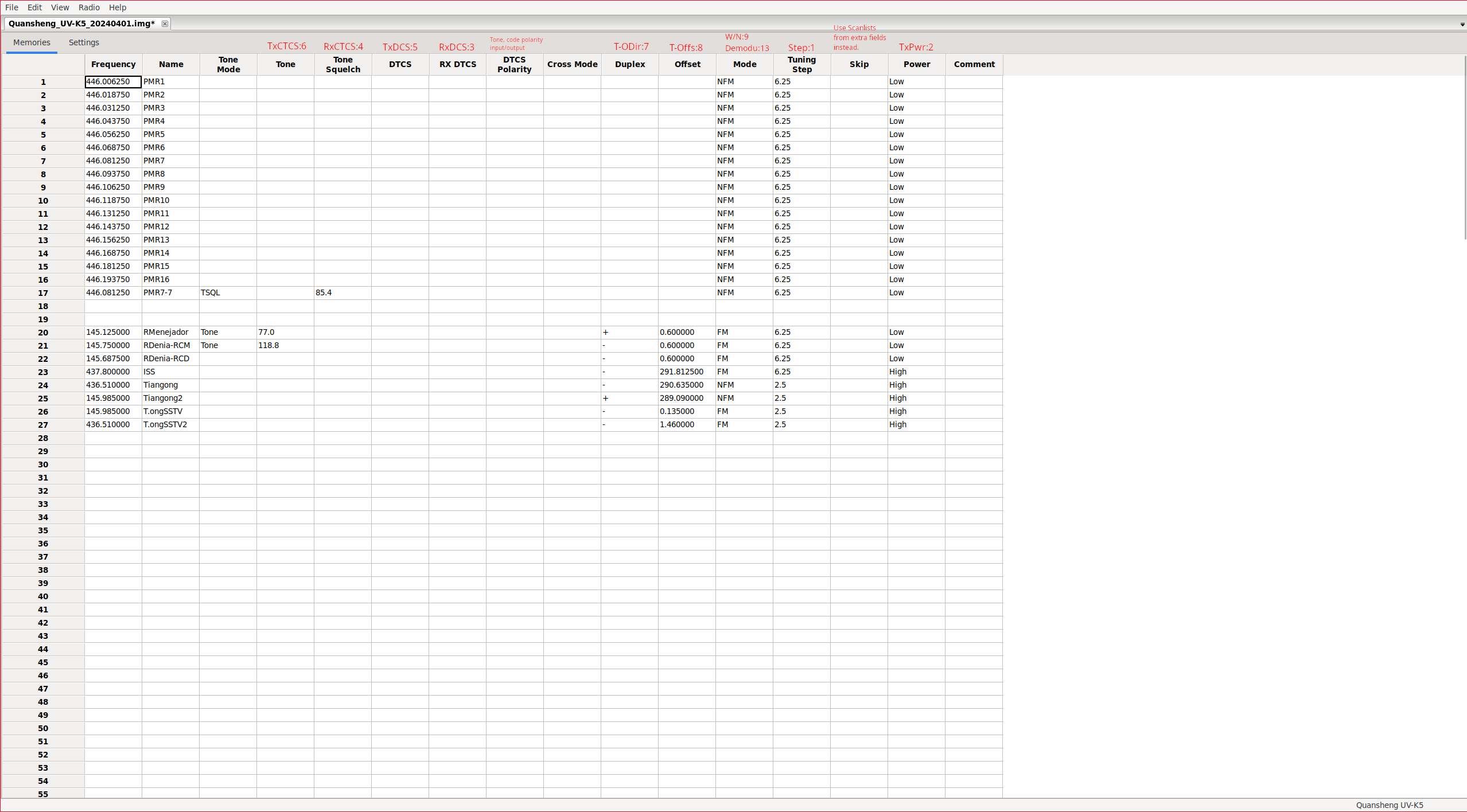
Channel list:
It will show us the channels. In my opinion, the interface leaves much to be desired since it’s very complicated to understand what each field is. It would have been much simpler to map a column for each option in the walkie’s menu, as
CPS
does. Despite its lack of intuitiveness, I will try to explain what
each parameter does:
NOTE: Skip column seems to be a bug, as for skipping a channel from scanning we only have to not assign it as scanlist member. To configure the scanlists we must enable extrafields(explained below).
The DTCS Polarity option specifies the polarity of the input/output tone/code . Tones only allow positive polarity (N), while digital codes allow both positive (N) and negative (R) polarity.
| Value. | Output polarity. | Input polarity. |
|---|---|---|
| NN | Positive | Positive |
| NR | Positive | Negative |
| RN | Negative | Positive |
| RR | Negative | Negative |
The Tone Mode option can take one of the following values:
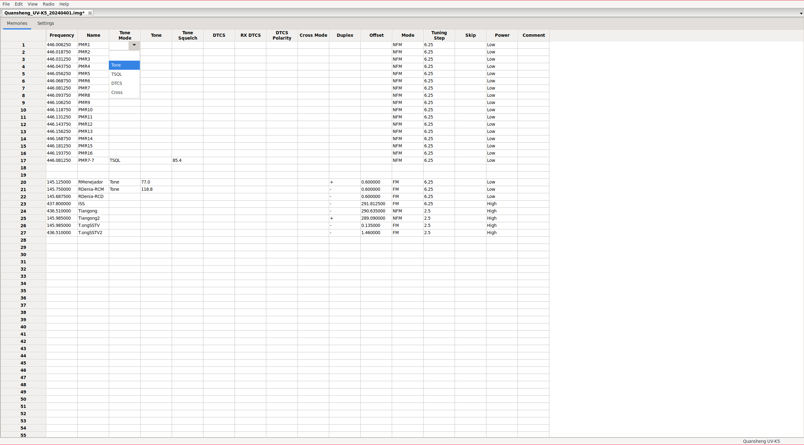
| Value. | Output Code/Tone. | Input Code/Tone. |
|---|---|---|
| None | No tone/code assigned | No tone/code assigned |
| Tone | Tone: Tone column | No tone/code assigned |
| TSQL | Tone: ToneSquelch column | Tone: ToneSquelch column |
| DTCS | Códe: DTCS column | Code: DTCS column |
| Cross | Mixed configuration. | Mixed configuration. |
NOTE: Cross: This mode should be assigned when we want to make mixed configurations, meaning not having only codes or only tones, but being able to choose for the input whether we will use codes or tones, and similarly for the output. This field depends on another column: Cross Mode.
The Cross Mode column determines whether codes or tones will be used, where the first field indicates transmission and the second field indicates reception:
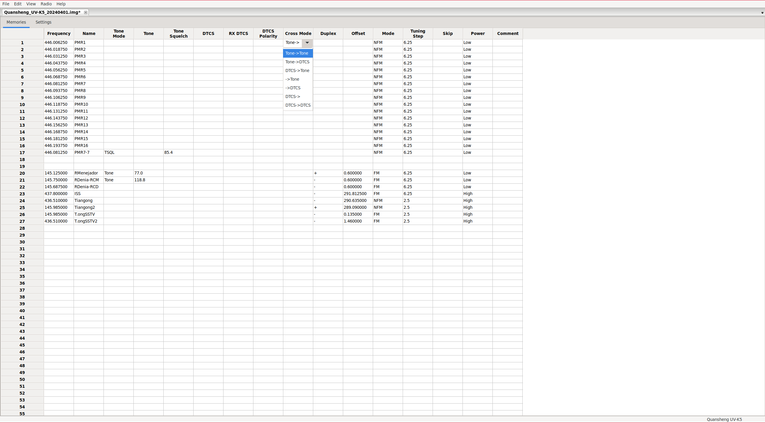
| Value. | Output Code/Tone. | Input Code/Tone. |
|---|---|---|
| Tone -> Tone | Tone: Tone column | Tone: ToneSquelch column |
| Tone -> DTCS | Tone: Tone column | Code: RX_DTCS column |
| DTCS -> Tone | Code: DTCS column | Tone: ToneSquelch column |
| -> Tone | No tone/code assigned | Tone: ToneSquelch column |
| -> DTCS | No tone/code assigned | Code: RX_DTCS column |
| DTCS -> | Code: DTCS column | No tone/code assigned |
| DTCS -> DTCS | Code: DTCS column | Code: RX_DTCS column |
NOTE: For some reason, the option Tone -> is missing, it’s a quirk of CHIRP, I suppose they’ll fix these kinds of issues over time. Remember that support for Quansheng is still experimental.
Some modes are more restrictive than others; for example, if we configure only digital code as output, it doesn’t make sense to have a tone set for input. The software detects these restrictions, but not very well; sometimes you have to click on more fields, even if you’re not changing anything, to apply these restrictions.
Band list:
Similarly to what we did with
CPS
, from CHIRP, it’s also possible to define the start and end of each band.
FM:            F1 50∽76 MHz
FM:            F2 108∽135.9975 MHz
FM:            F3 136∽173.9975 MHz
FM:            F4 174∽349.9975 MHz
FM:            F5 350∽399.9975 MHz
FM:            F6 400∽469.9975 MHz
FM:            F7 470∽599.9975 MHz
FM:            F7+ XXXXX-XXXXX MHz
AM:            F2 108∽135.9975 MHz
To modify the parameters, we need to scroll down to the bottom of the channel list.
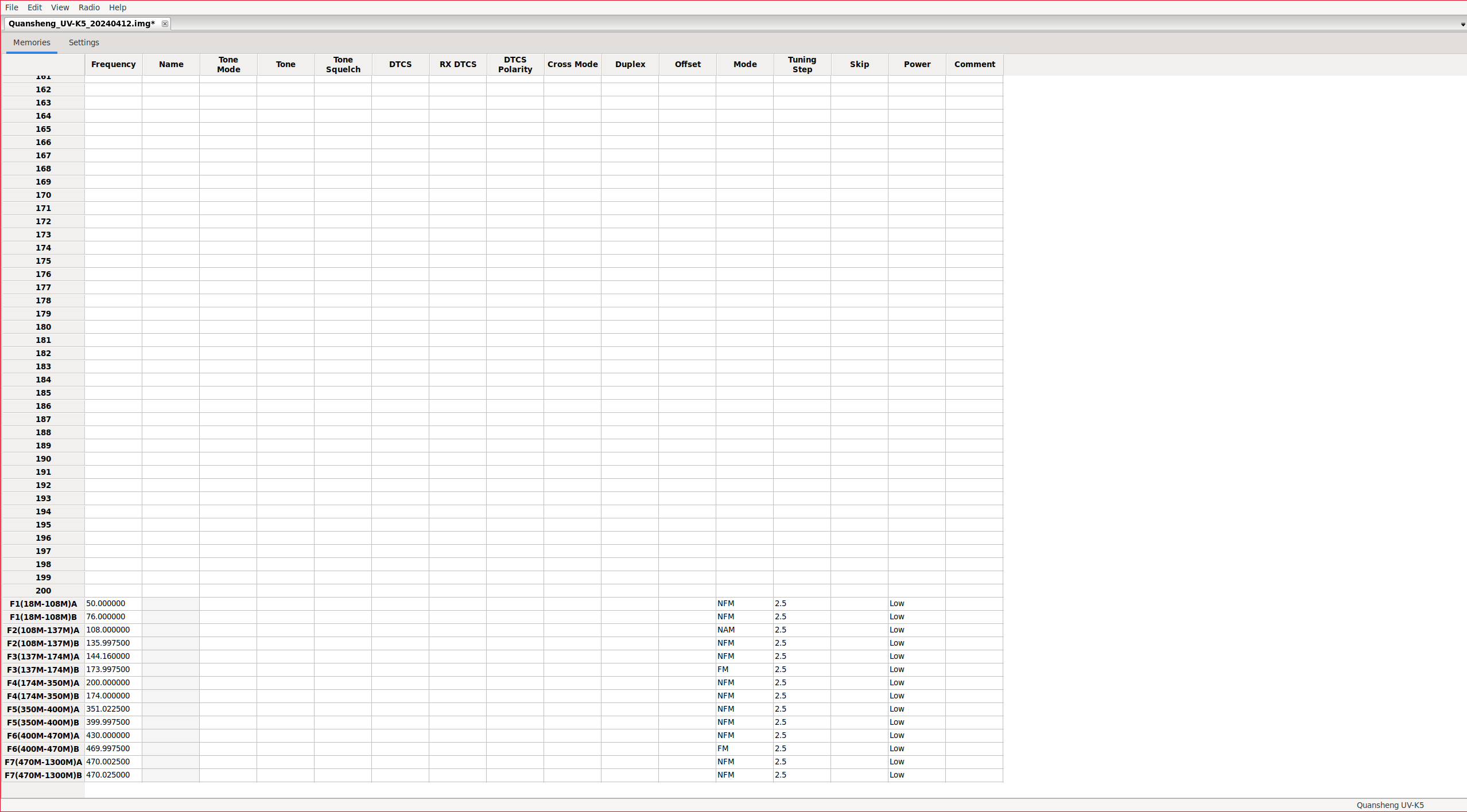
By modifying these parameters, we will alter the frequency limits when scanning in a band and the default parameters in the bands such as tones/codes , the bandwidth, transmission power, and other parameters. Of course, we can always modify these parameters on-the-fly from the walkie’s menu.
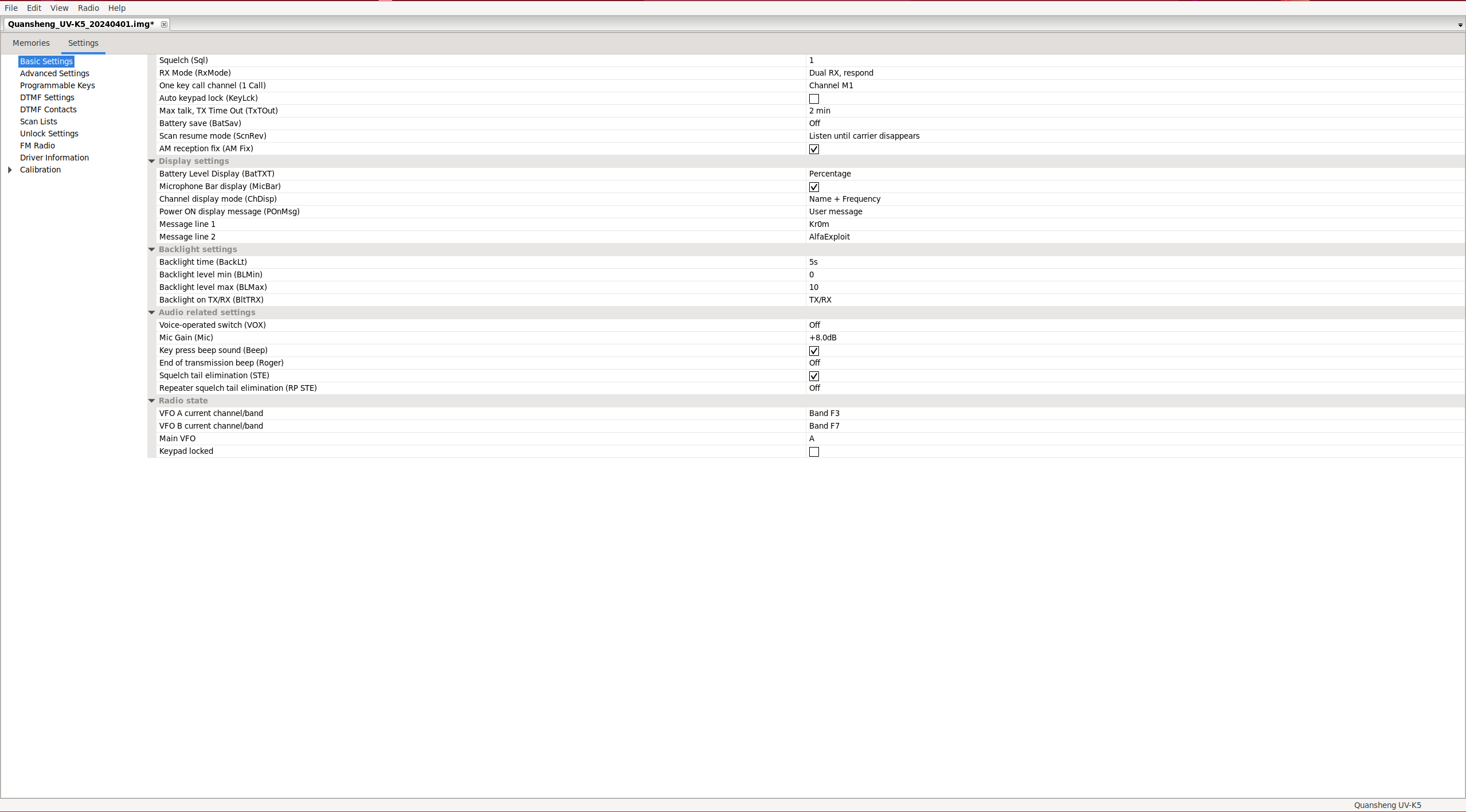
Settings:
In the Settings tab, we can find the rest of the configuration.
Basic Settings: As we can see, EGZUMER has taken the detail of indicating which parameter of the walkie each option corresponds to.
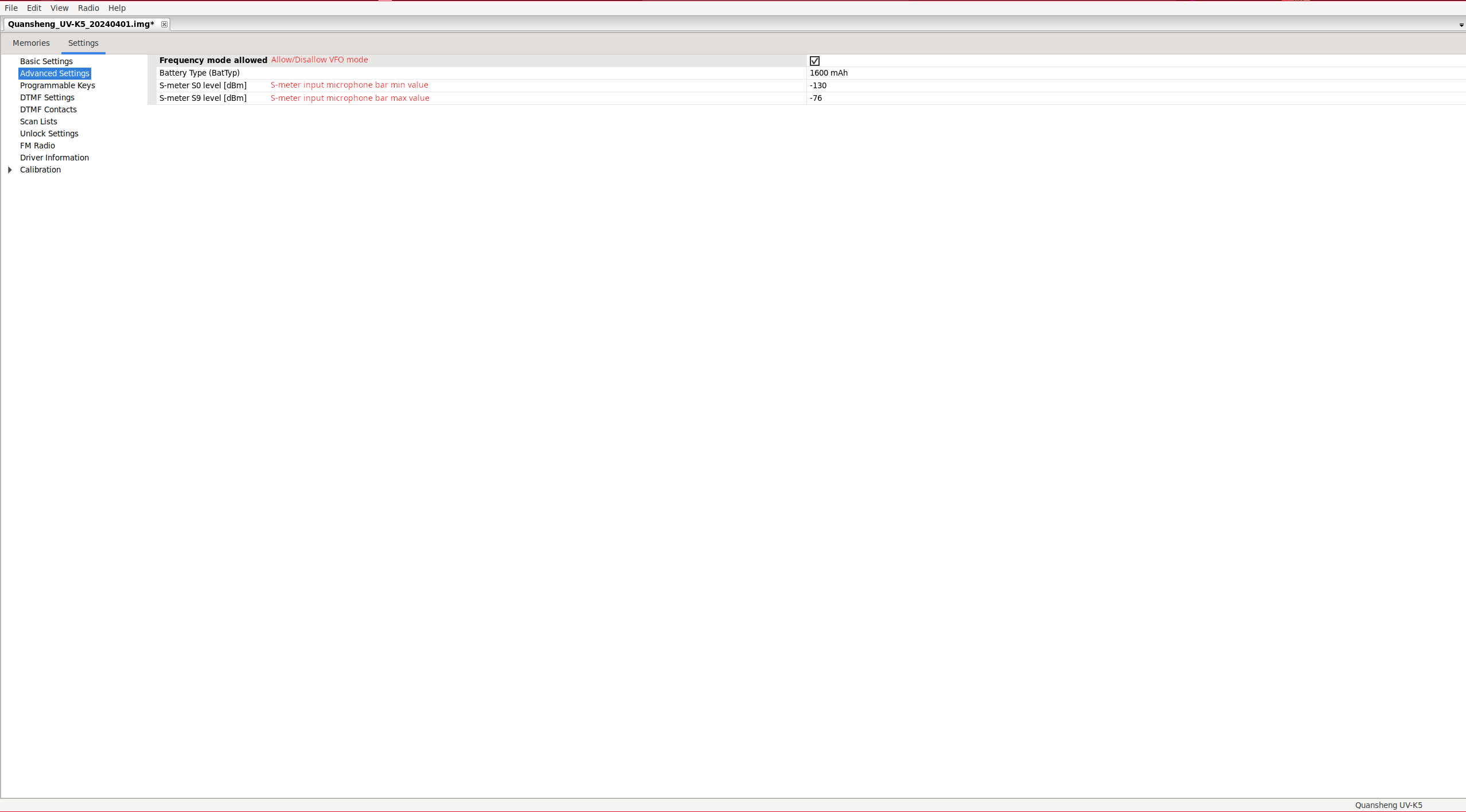
Advanced Settings:
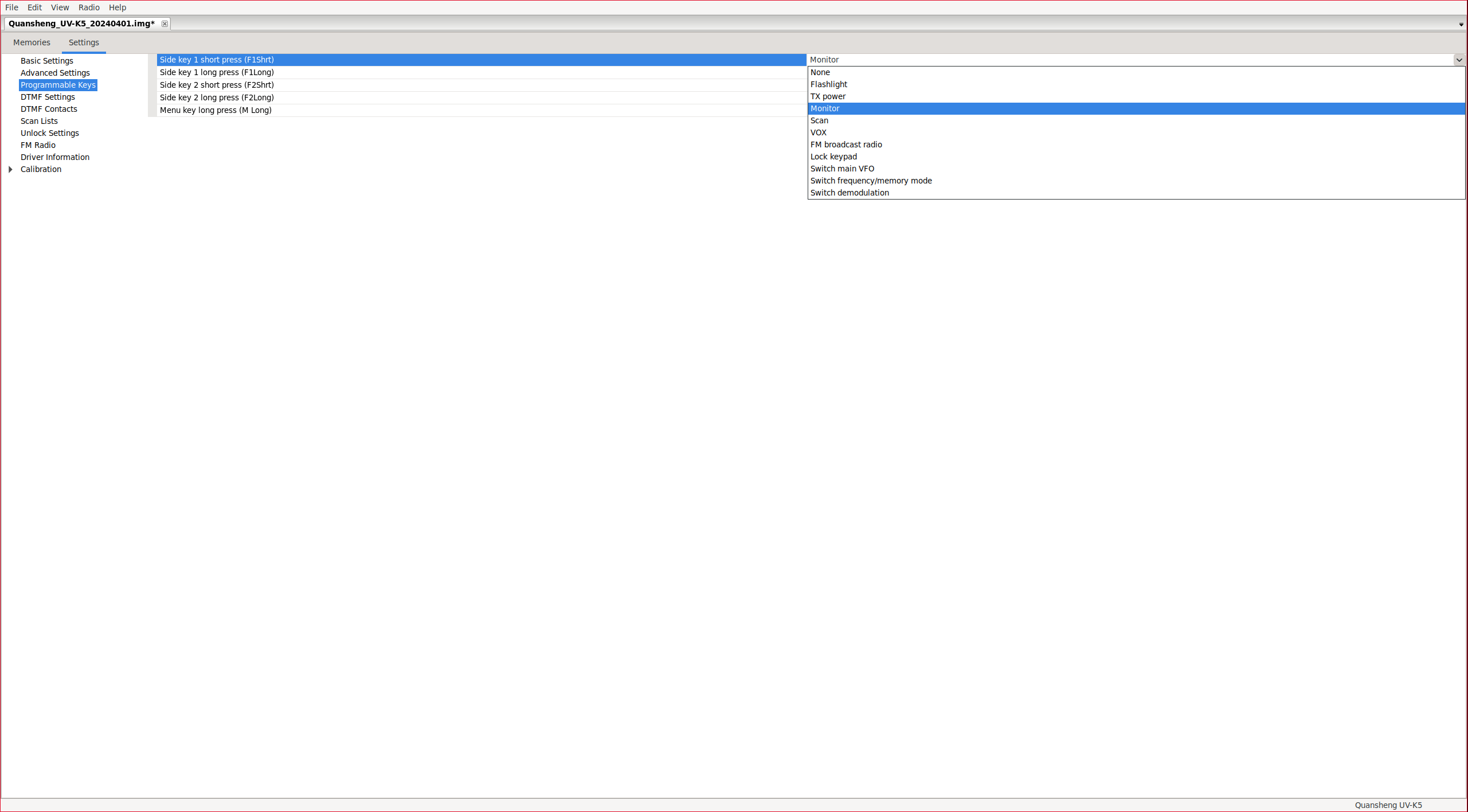
Programmable keys: SideKeys configuration.
DTMF Settings: DTMF parameter configuration.
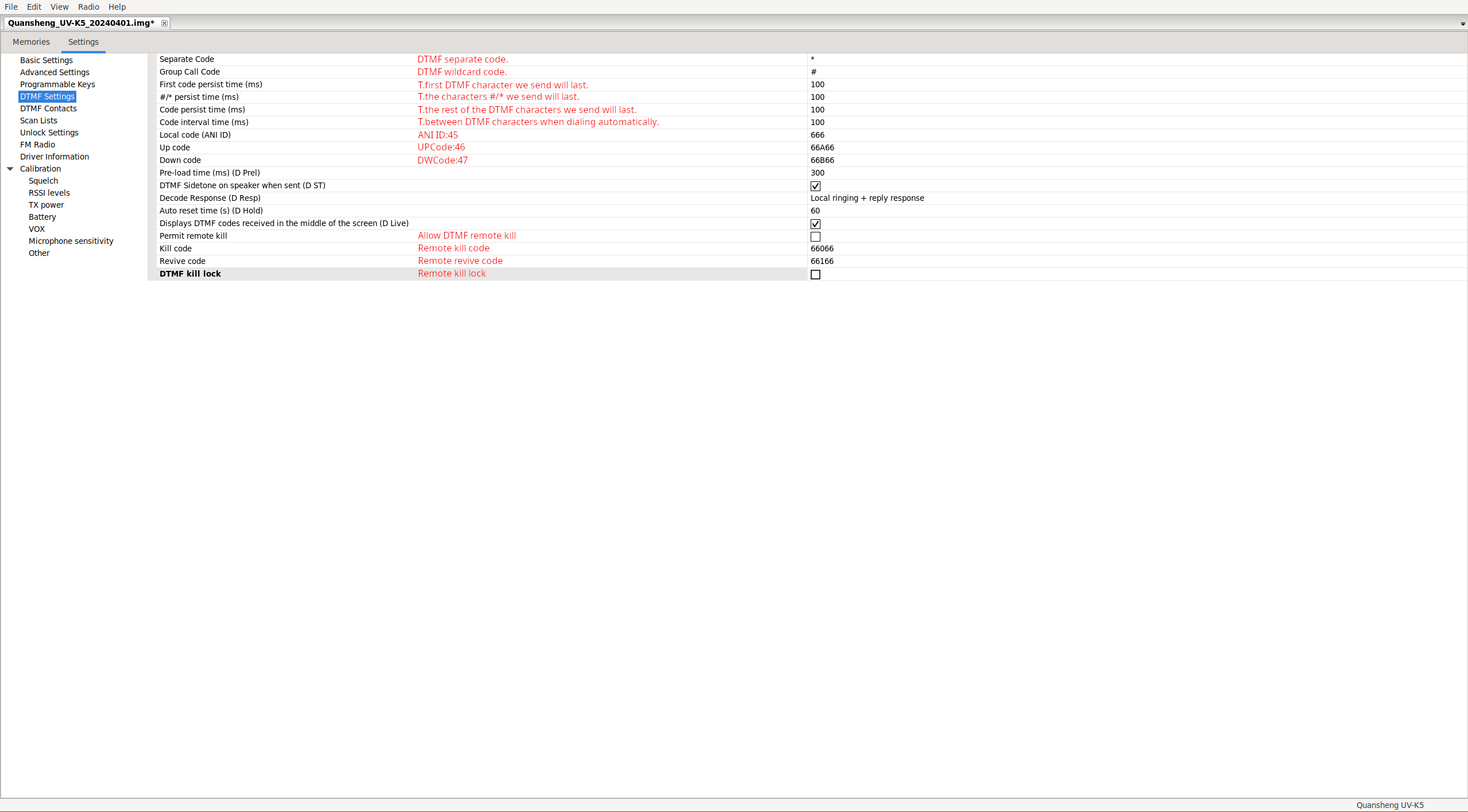
NOTE: We must consider that the DTMF remote kill functionality doesn’t work correctly under EGZUMER.
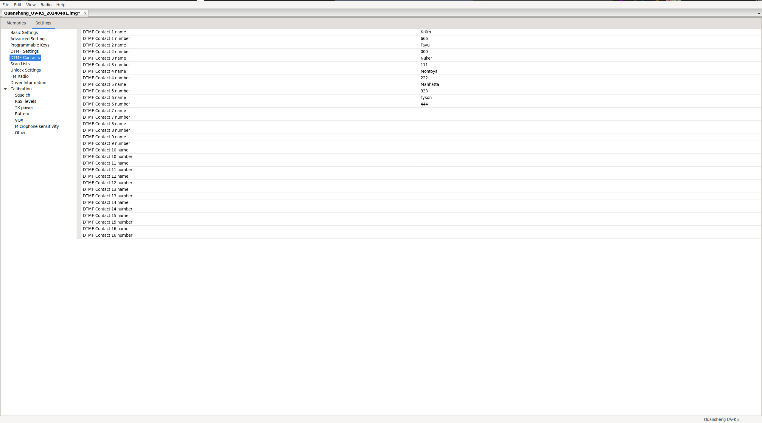
DTMF Contacts: DTMF contact configuration.
Scan Lists: From this section we can only assign the default scan list, enable/disable scan priority, and configure the two priority channels for each list. These are channels that will be scanned more frequently than non-priority ones. This is useful when scanning a large number of channels without missing the reception of a priority channel while the walkie is busy scanning non-priority channels. To edit the lists, we must do so from the Memories tab, after previously enabling the extra fields: View → Show extra fields, as explained below.
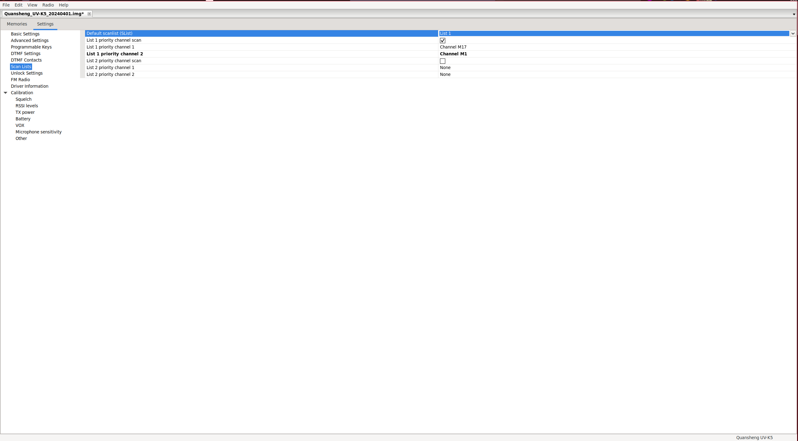
When configuring a priority channel, it is added to the scan list even if it does not appear in Memories as part of the list. Additionally, it seems that when configuring priority channels in the list, EGZUMER stops displaying the contents of the lists correctly. It only shows the first non-priority channel of the list and the priority channels. However, scanning still functions correctly despite the incorrect display of information.
Unlock Settings: It allows us to unlock transmission on frequencies outside the amateur radio range in the same way we did from the
extended menu
.
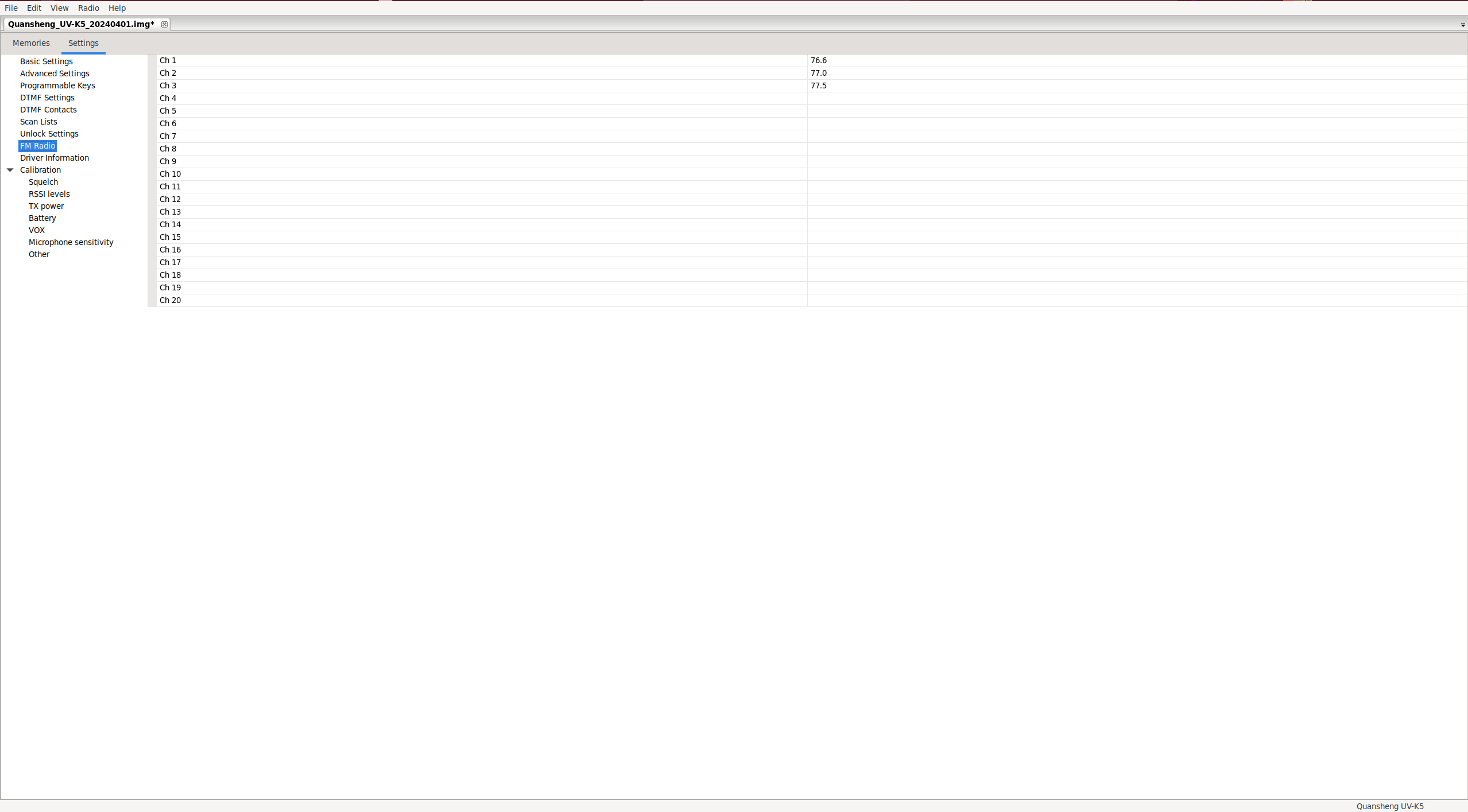
FM Radio: It allows editing of the stored radio channels.
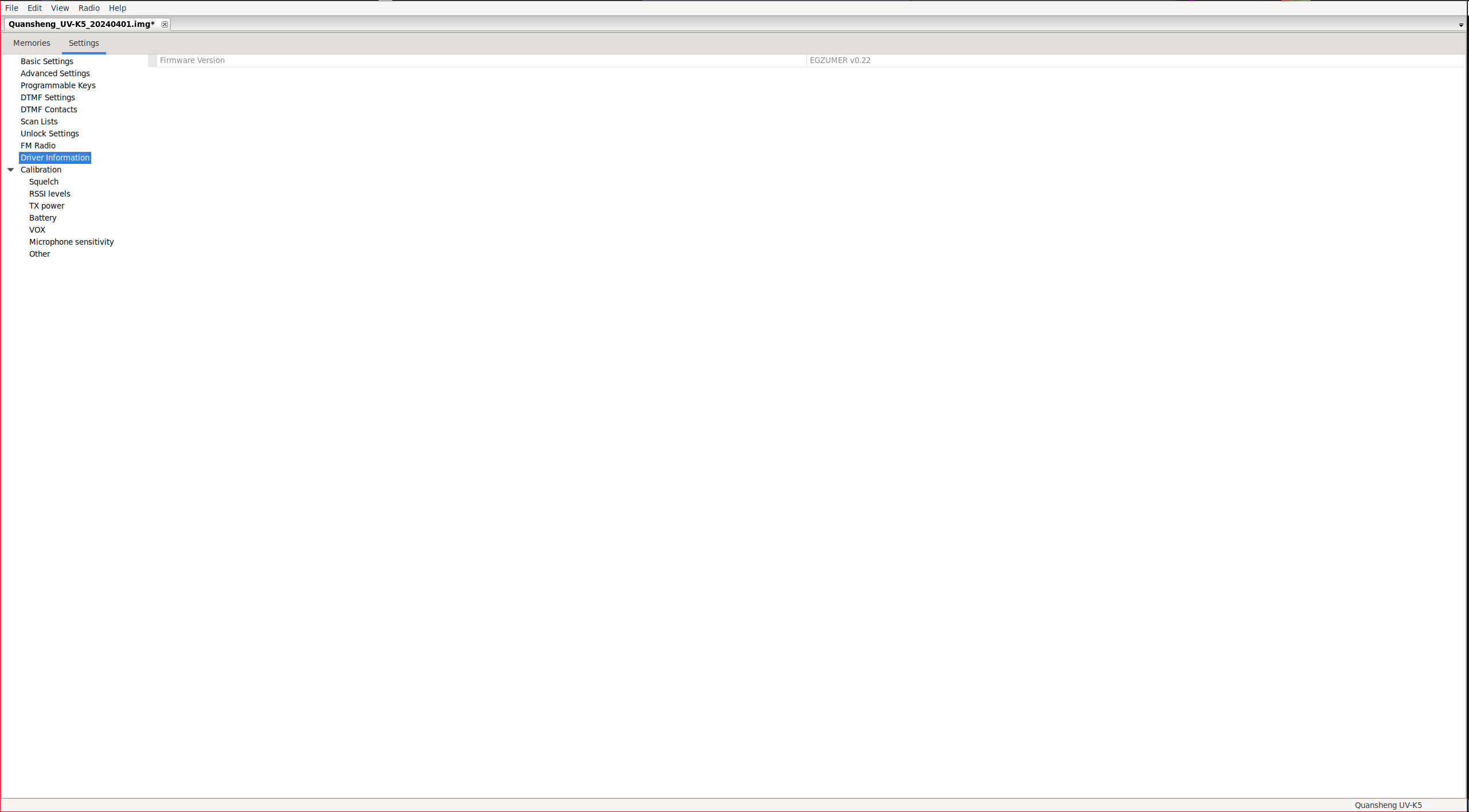
Driver information: Shows firmware version.
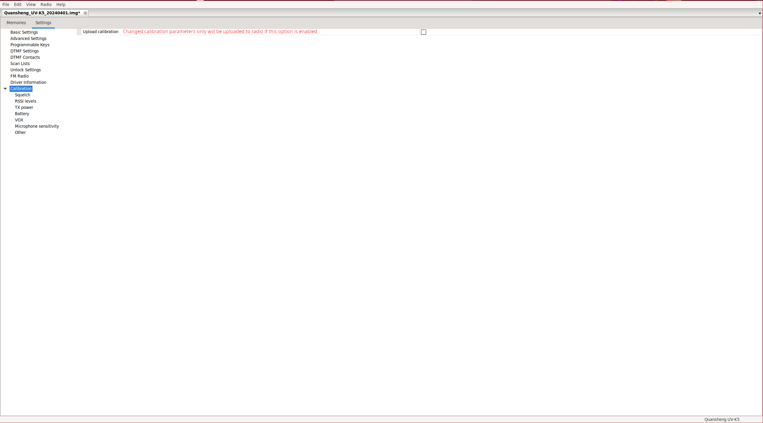
Calibration: It allows adjusting calibration parameters. As indicated on the
EGZUMER website
,
CHIRP
saves the radio’s calibration parameters in the files it generates when saving. Therefore, if someone passes us their file and this option is enabled, we will be loading their calibration. The best way to backup our calibration is using
k5prog-win.
There are some parameters that the
EGZUMER firmware doesn’t use at all
, Chirp displays the values stored in the EPROM, but they are not used for anything.
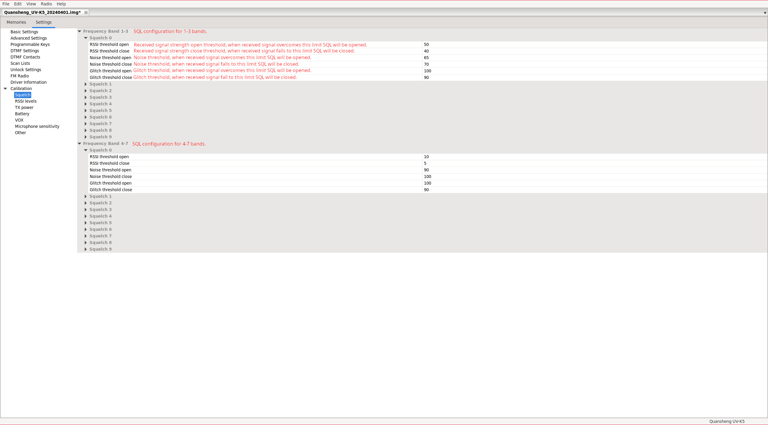
Calibration-Squelch: It allows adjusting the parameters for each squelch level (60), only two configurations are allowed, one for the first three bands and another for the next four.
These values are read and multiplied by two by the firmware.
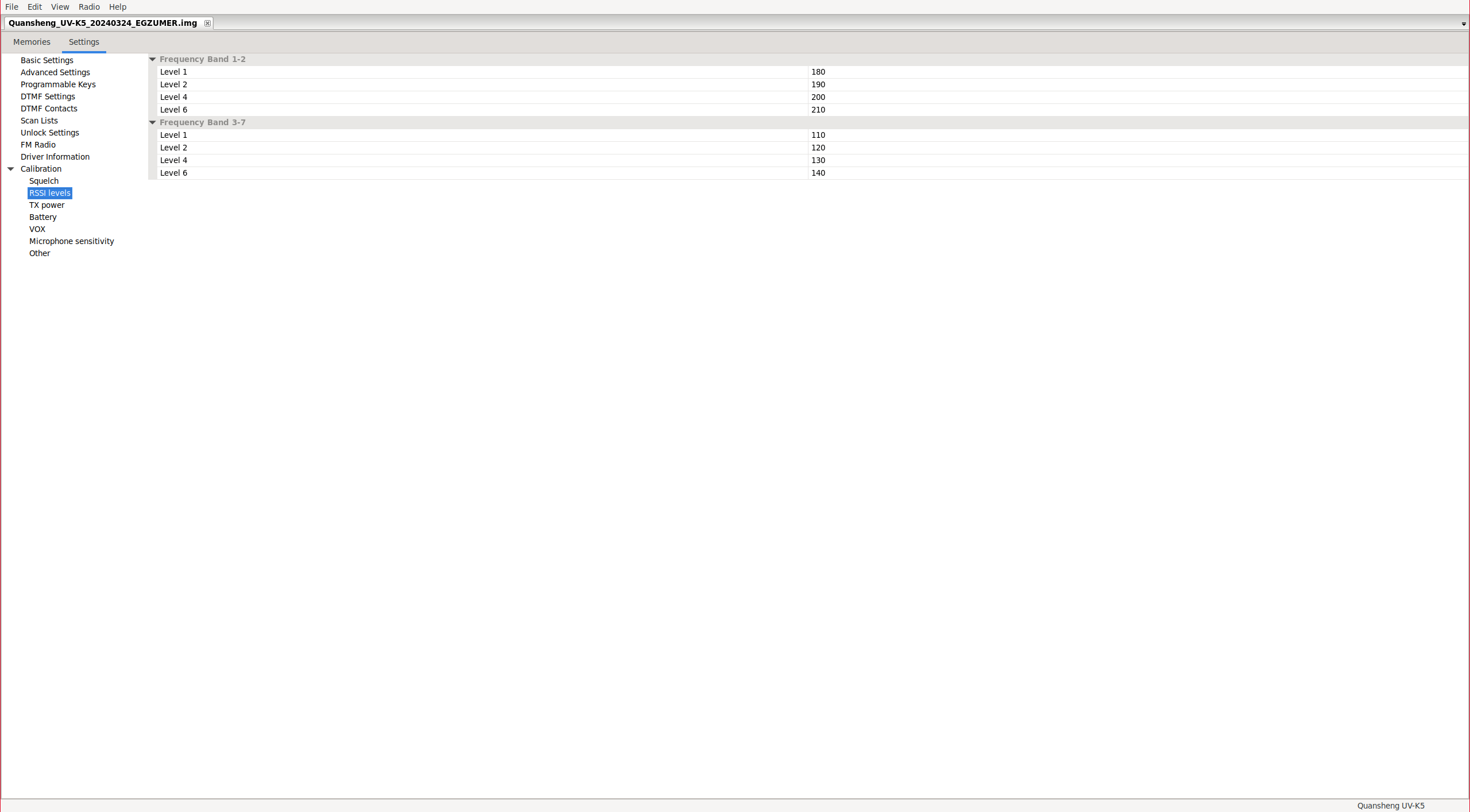
Calibration-RSSI levels: We can define the thresholds for the quality of the incoming signal to display X or Y bars, it only allows two configurations, one for the first three bands and another for the next four.
It is only used if the firmware was compiled with the option ENABLE_RSSI_BAR=0.
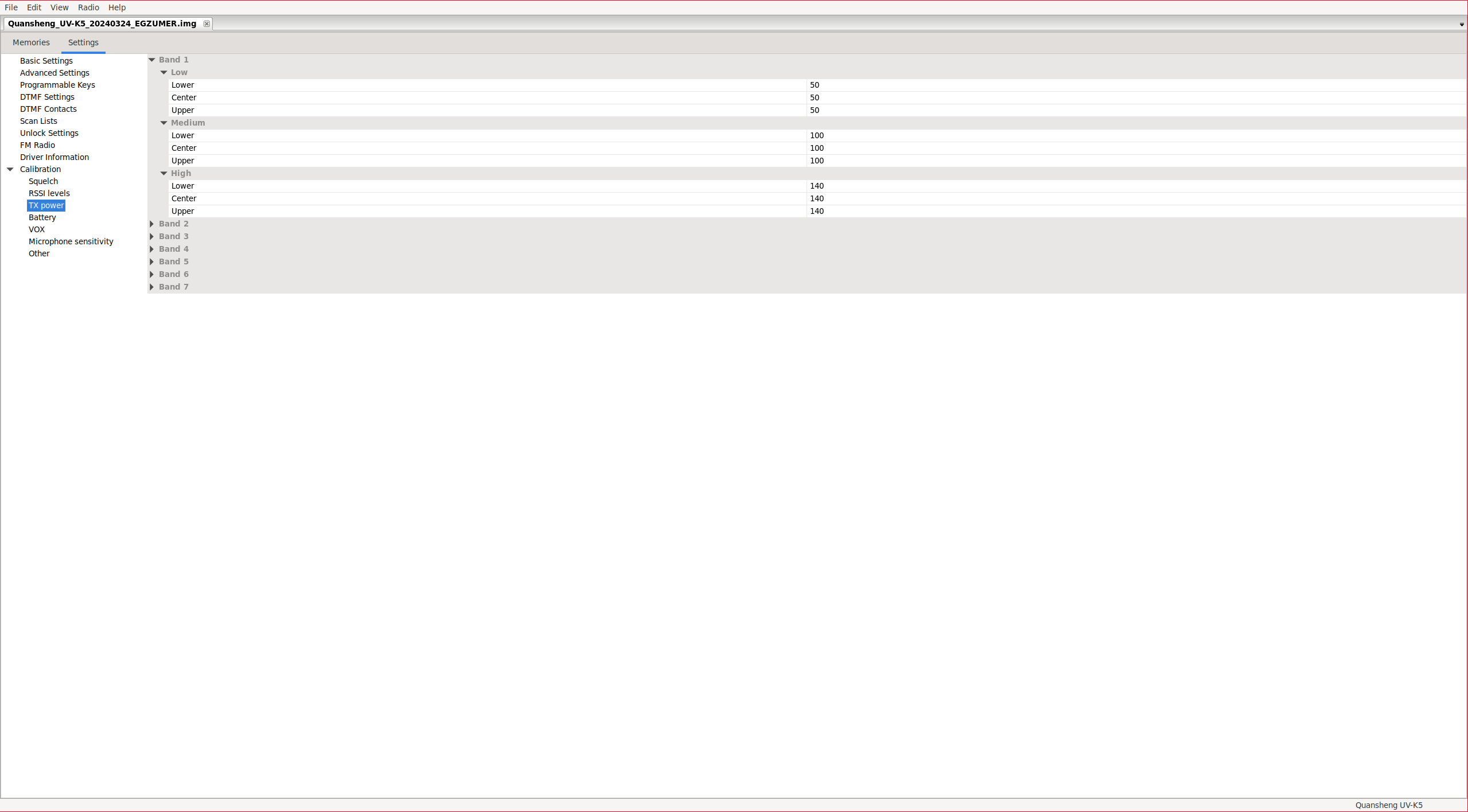
Calibration-TX power: Allows defining the power level for transmitting in each band. If the firmware is compiled with the option ENABLE_REDUCE_LOW_MID_TX_POWER enabled the value of the medium power is divided by 3 and the low power by 5.
You can see the values Lower/Center/Upper because the bands are divided into regions of XMHz. Depending on the region of the band in which we are operating, different power levels will be applied. For example, if we are in band F1 with the walkie configured in Low power, while remaining in the low region, we will transmit at: Band 1 -> Low -> Lower. However, with the same configuration in the high frequencies of band F1, it would be: Band 1 -> Low -> Upper.
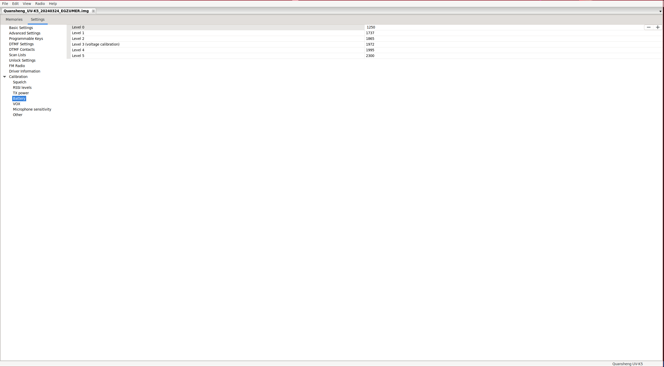
Calibration-Battery:
Only is used level 3.
This value is configured using the
battery calibration procedure.
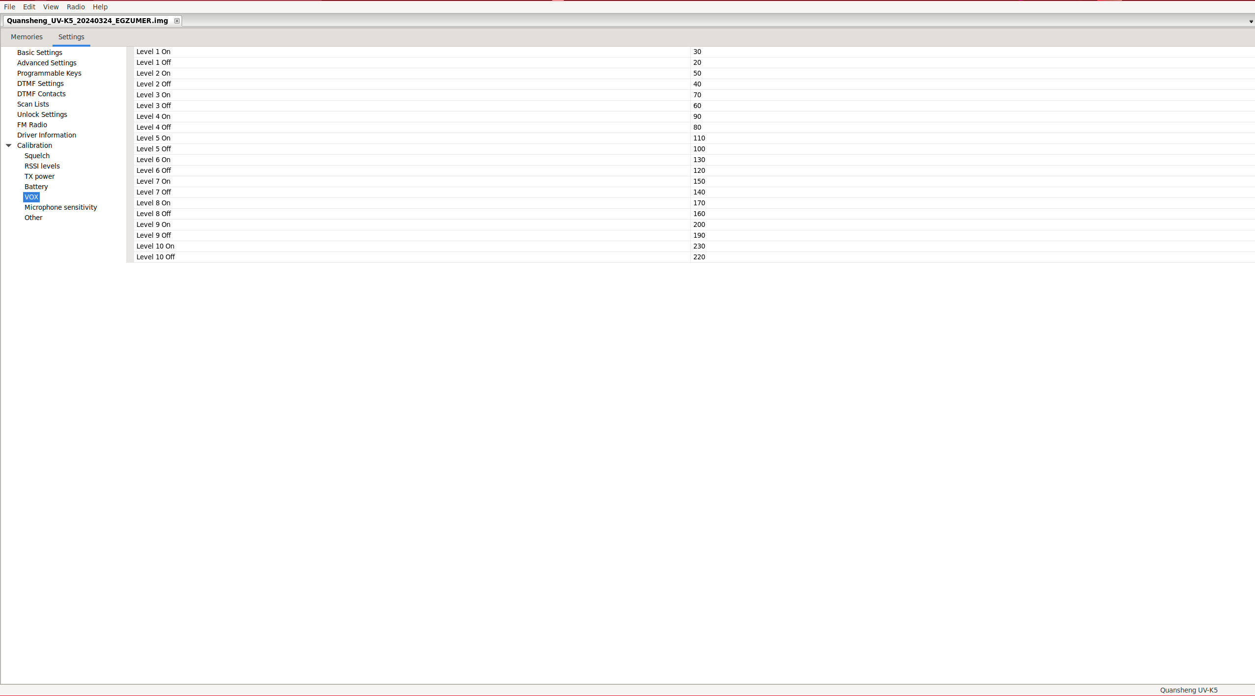
Calibration-VOX: It allows you to define the VOX activation thresholds for each of the levels.
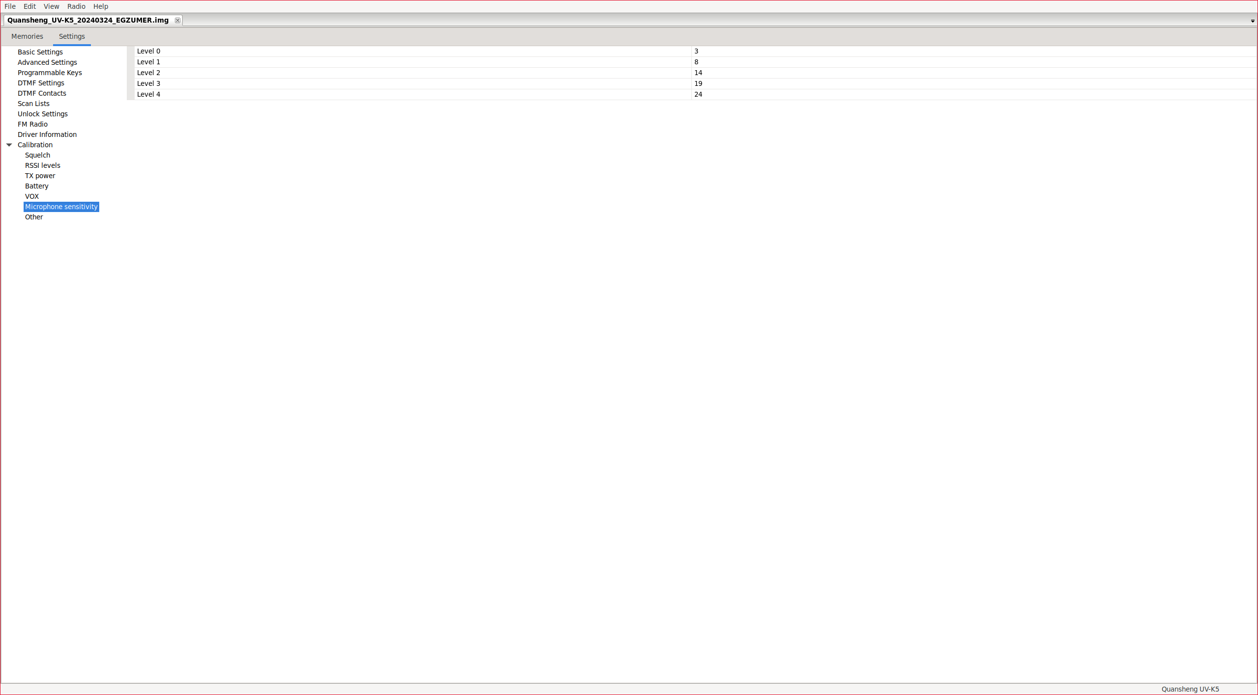
Calibration-Microphone sensitivity:
It’s not used.
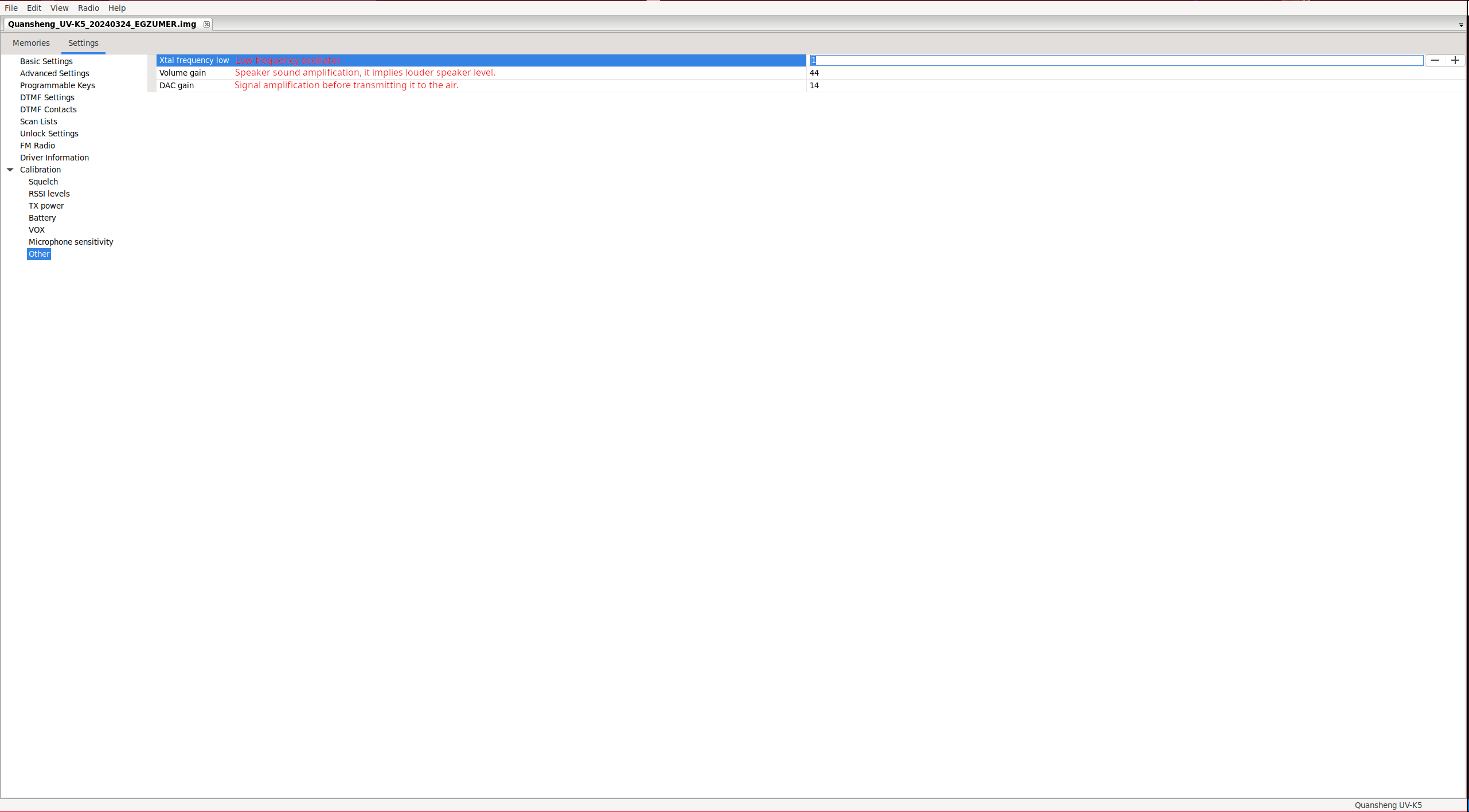
Calibration-Other: Crystal frequency, volume and DAC gain tunning.
According to the radio chip datasheet, , the walkie comes with a 26MHz crystal and there is a variable capacitor that is used for crystal frequency calibration:
Cvar is an adjustable capacitor for frequency calibration.
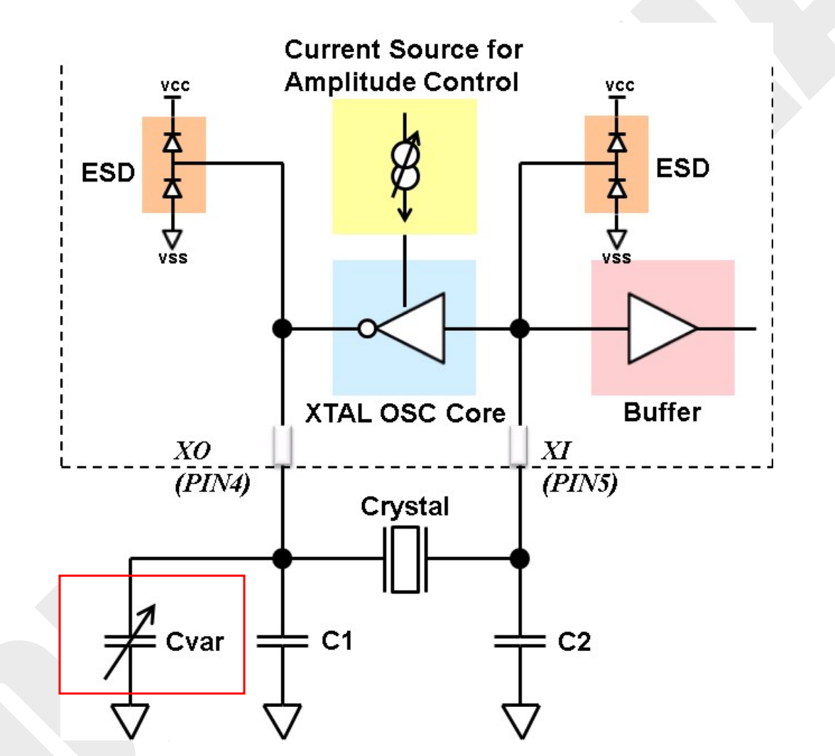
I imagine that a 26MHz crystal is considered low frequency, and for this reason, Xtal frequency low receives a default value of 1. I don’t think this parameter needs to be adjusted unless we make hardware modifications to the walkie.
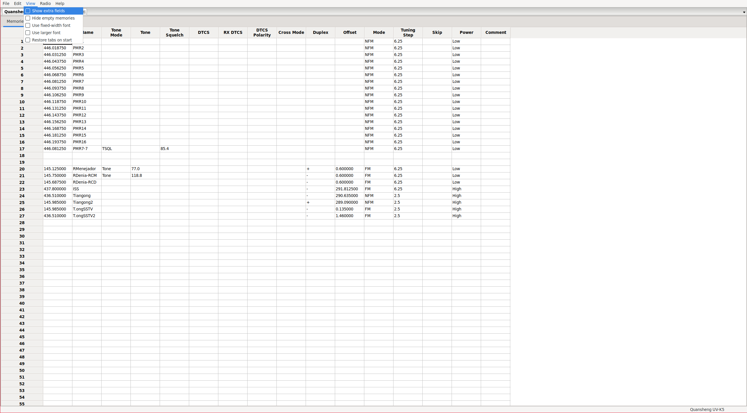
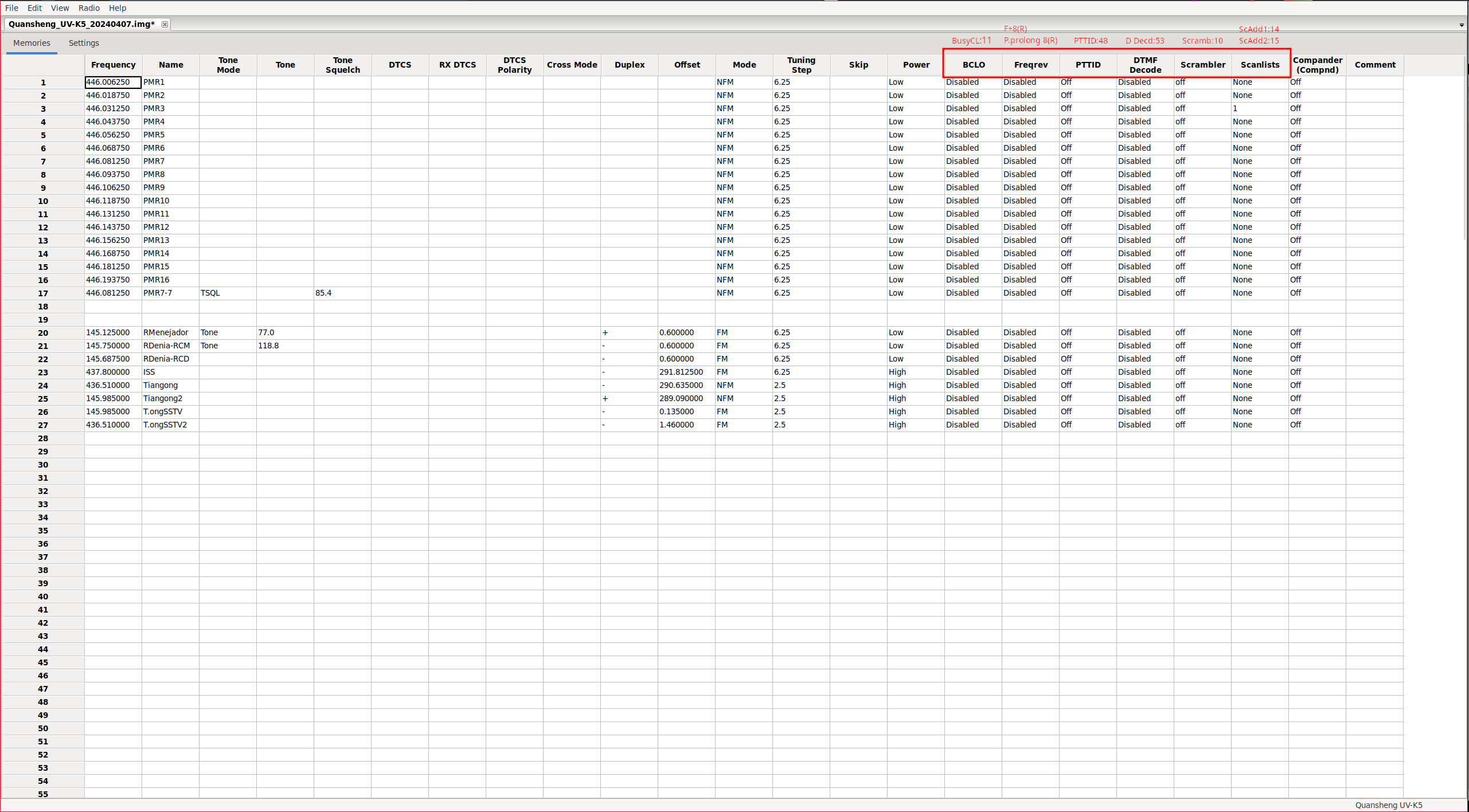
Extra fields:
In the Memories section, you can display some additional parameters if you enable them.
View -> Show extra fields
|
|
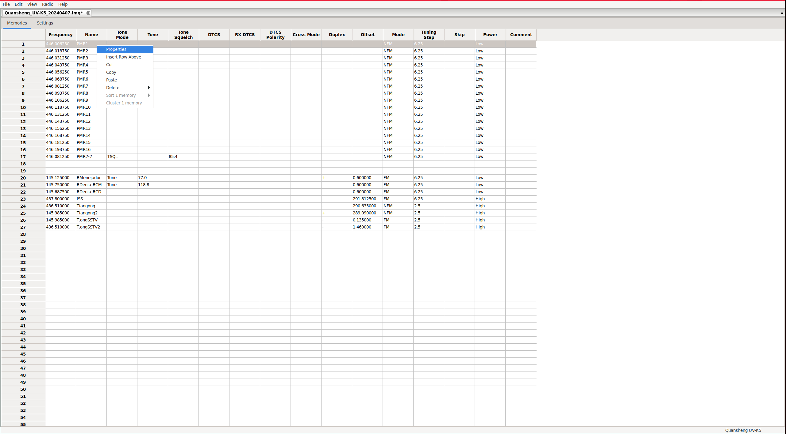
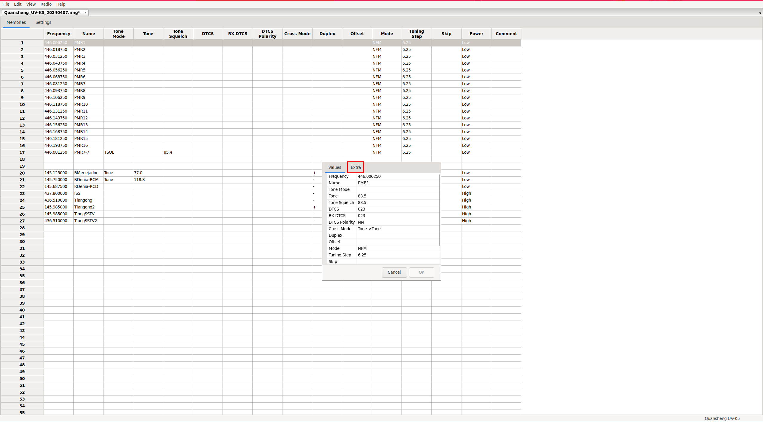
Actually, these parameters can also be accessed without enabling the mentioned menu. You should click on:
Right click on the channel -> Properties -> Extra Tab
|
|
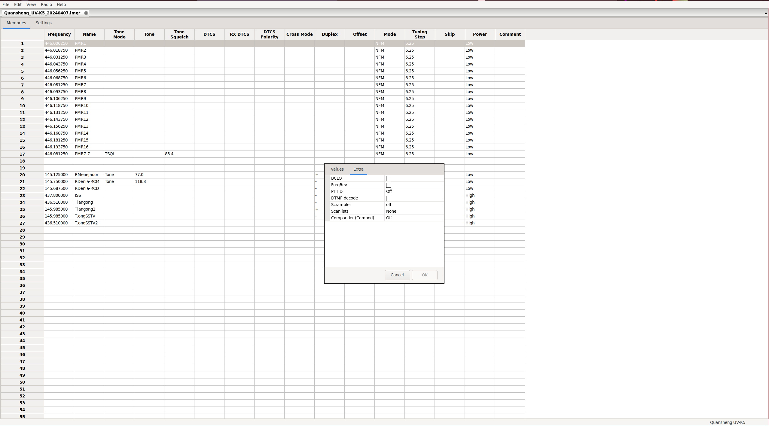
|
It seems that CHIRP is quite buggy as of today, at least with this walkie model. For example, we can see in channel 20 that there is ONLY an analog tone configured for output, but in Properties, we see digital tones and other settings.

Bugs:
This firmware presents a serie of bugs to take into account:
- DTMF calls between firmware versions, the issue is detailed in the DTMF calls section.
- Kill code functionality appears to be completely broken, as described in detail in the Remote kill section.
- There is a bug related to the information displayed in ScanLists when including priority channels (Scan Lists section) in the list; it stops showing the content correctly, only displaying the first non-priority channel of the list and the priority ones.
- Battery calibration shown value.