IJV is an alternative firmware for our beloved Quansheng K5(8)/K6(buy link) , it offers a series of very interesting features, especially regarding signal reception, a more advanced interface in the main menu and submenus, and the management of up to 999 channels through the replacement of the EEPROM memory.
The main advantages that IJV offers over the stock firmware are:
- Better interface with stacked windows, similar to contextual menus.
- Allows the input of frequencies above GHz in single-channel display mode.
- AGC: Adjustment of the incoming signal gain. Manual for FM, automatic for AM and SSB.
- DSB transmission emulation (Double SSB).
- Possibility of using an external Upconverter to expand the supported frequency range (reception only).
- Rit & Xit.
- Stable reception on SSB.
- SATCOM circuit activation with reception boost > +9dB.
- QRA (ID in CW mode).
- Adjustment of the 3 transmission power levels.
- Adjustment of the 9 Squelch levels: RSSI, NOISE, GLITCH.
- Compander.
- Extended reception frequency range: 15 - 1300MHz, with a gap from 620 - 840MHz.
- Quick frequency/tone search: FC (Frequency Copy).
- Quick tone search.
- Channel list, band or frequency range scanning.
- SMETER indicator.
- Modulation indicator during transmission.
- DTMF, ZVEI, CCIR tone support.
- CW (Continuous Wave) modulation, morse.
On the other hand, some concessions had to be made since space is limited:
- Spectrum analyzer.
- Power on password.
- NOAA support.
- VOICE: The annoying menu voices have been removed.
- ALARM: The alarm functionality has been removed.
- Battery percentage indicator.
- Blinking LED.
- USB charging information.
- AirCopy.
- Remote kill functionality
If you are new to the world of amateur radio, I recommend this previous article where the basics are explained.
The article is composed of the following sections:
- 999 channels
- Reflash
- Functions
- Buttons and functions
- Screen indicators
- Scan function
- DTMF calls
- Frequency scanner
- Frequencies above 1000 MHz (GHz)
- Rit/Xit
- Scrambling
- CHIRP
- Bugs
999 channels:
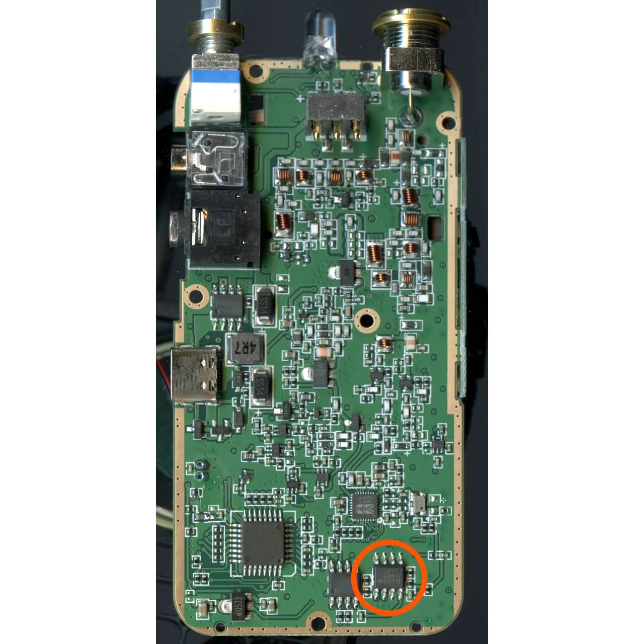
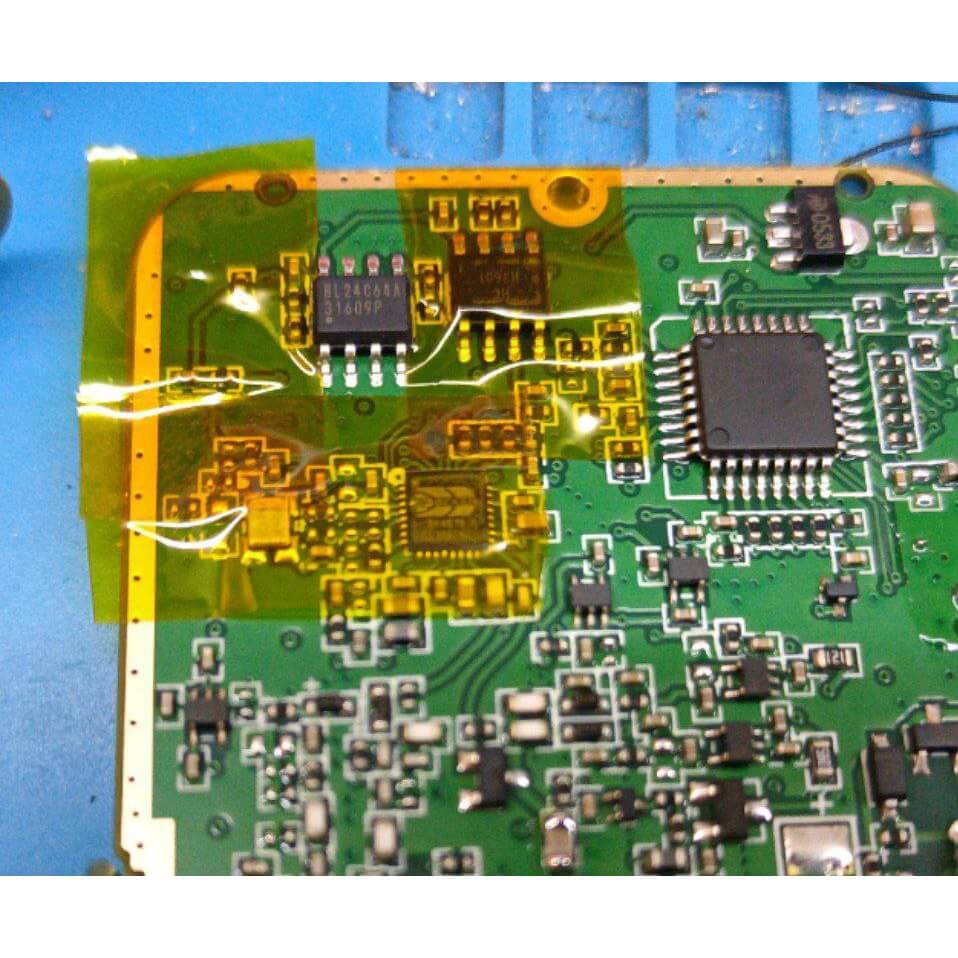
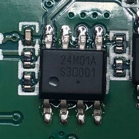
By replacing the 8K EEPROM (24C64) with a 128K EEPROM (24M01) and loading the correct IJV image, we can increase the capacity of stored channels in the radio from 200 to 999.
We can see the location of the EEPROM in the following images:
| Board location | 24C64 | 24M01 |
|---|---|---|
|
|
|
The firmware version depends on whether we have made the hardware modification:
firmware_IJV_V3.bin  ⇒ 200 channels.
firmware_IJV_VX3.bin ⇒ 999 channels.
If we load the firmware version firmware_IJV_V3 on a radio with the hardware modification, it will still show 200 channels.
However, if we load the firmware version firmware_IJV_VX3 on an unmodified radio, it won’t detect any saved channels; it can only operate in VFO mode.
Reflash:
Before we begin, we need to install Mono on Wine-Linux, and then proceed to make a backup of the configuration and calibration files as indicated in this previous article.
It is also recommended to save the current radio configuration, as this will be useful later to load the channels into the new firmware. We save it twice, in both CHIRP and CSV formats, because if there are issues loading, the CSV file can be edited in order to alter or remove the problematic fields.
To create the backup, just follow these steps in
CHIRP
:
Radio -> Download from radioFile -> Save As ...File -> Export to CSV ...
Now we can proceed with the re-flashing. First, we download k5prog as indicated on the IJV website. There’s also the option of using the web flasher , but in my case, it doesn’t work under FreeBSD, so I prefer the VM-Wine-Linux option.
Depending on whether we have made the hardware modification to have 999 channels, we will download one version or the other of K5prog:
mkdir IJV
cd IJV
wget https://www.universirius.com/SirioArchive/Materiel_pr_site/Firmware-IJV/K5prog_IJV_V3.zip
unzip K5prog_IJV_V3.zip
mkdir IJV
cd IJV
wget https://www.universirius.com/SirioArchive/Materiel_pr_site/Firmware-IJV/K5prog_IJV_VX3.zip
unzip K5prog_IJV_VX3.zip
We download the firmware; the compressed file is generic regardless of whether we have made the hardware modification, as it contains both images:
unzip index.html\?file\=firmware_IJV_V3.zip
In this compressed file, we will find:
  changelog.txt                         Changes between versions.
  firmware.IJV_V3.18.bin                Non modified hardware firmware image.
  firmware.IJV_VX3.18.bin               Modified hardware firmware image.
  installazione modulo per chirp.pdf    Instructions in Italian on how to load the module in CHIRP.
  useful links.txt                      Some useful links related to IJV.
  uvk5_IJV_v3_43.py                     CHIRP module for the version without hardware modification.
  uvk5_IJV_vX3_43.py                    CHIRP module for the version with hardware modification.
We start the walkie in reflashing mode:
PTT button + switch on the radio.
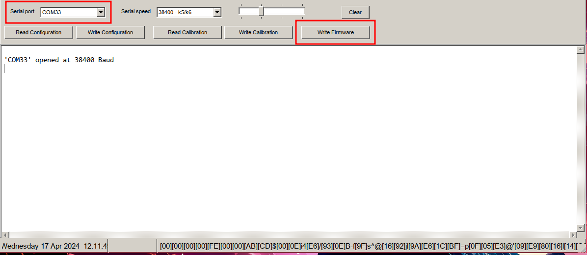
Start k5prog:
Before reflashing, we make sure to have enough battery in the walkie.
| We specify the serial port and the firmware image. | We select the correct image. |
|---|---|
|

|
Once reflashed, we’ll need to perform a Reset ALL. This step is required regardless of whether we’ve switched from a different firmware to IJV or if we’ve updated between IJV versions or from IJV-V3 to IJV-VX3. It’s always required.
We start the walkie in extended menu mode:
PTT button + SideKey1 + switch on the radio.
RESET menu entry: ALL
We can see the exact procedure in the following video:
To avoid losing channels during a firmware migration or an update within IJV, we must have backed up the channels as indicated at the beginning of this section of the article and follow the following steps from CHIRP to restore them:
- Open a backup file from any firmware.
- Copy the channels from the Memories tab.
- Read the data from the radio:
Radio -> Download from radio. - Paste the copied channels from the backup.
- Upload the configuration:
Radio -> Upload to radio.
NOTE: This procedure seems to have issues. When pasting, it appears as if nothing has been done. However, if we upload the configuration to the radio and then download it, we’ll see that the channels appear pasted but in the incorrect order, the scan lists don’t appear in the dropdown, all channels have a squelch of 0. It seems that migrating the channel memories is not a good idea, at least in IJV.
For greater convenience, I have configured an alias to run the software more easily:
alias quanshengK5prog='WINEARCH=win32 WINEPREFIX=~/.local/share/wineprefixes/wineprefix32 wine ~/K5prog_IJV_V3.exe'
Functions:
| Option | Menu-ID | Function |
|---|---|---|
| SQL | 1 | Each channel has its own Squelch. To adjust them independently, we first need to disable DualRX(56). |
| STEP | 2 | How many kHz/Hz will it advance or retreat when we scan or manually change the frequency. |
| MODE | 3 | Change the modulation technique : |
| FM: By default. | ||
| AM: Only reception. | ||
| DSB: Only reception. | ||
| CW: Only reception. | ||
| WFM: Only reception, comercial radio. | ||
| BW W/N | 4 | Adjust both the audio filter and the bandwidth to be used: The saved channels will automatically store this parameter without the need to re-save the channel. |
| W - Audio filter: 25 kHz / Bandwith: 25 kHz. | ||
| W - Audio filter: 22 kHz / Bandwith: 25 kHz. | ||
| W - Audio filter: 18 kHz / Bandwith: 25 kHz. | ||
| N - Audio filter: 12.5 kHz / Bandwith: 12.5 kHz. | ||
| N - Audio filter: 8 kHz / Bandwith: 12.5 kHz. | ||
| N - Audio filter: 6 kHz / Bandwith: 12.5 kHz. | ||
| U - Audio filter: 3 kHz / Bandwith: 6,25 kHz. | ||
| U - Audio filter: 2 kHz / Bandwith: 6,25 kHz. | ||
| Tx PWR | 5 | Adjust the transmission signal power: The saved channels will automatically store this parameter without the need to re-save the channel. The same power level can vary depending on the loaded Preset(54). For example, HIGH in the PMR preset is 4.2W, while in the VHF 144 preset, it is 4.8W. When pressing the PTT in single-channel mode, we can observe the power being used. |
| LOW: Low power level. | ||
| MID: Medium power level. | ||
| HIGH: High power level. | ||
| Shift | 6 | Apply the offset in positive (+) or negative (-), used in repeaters. |
| Offset | 7 | Offset to be applied in repeaters. |
| RxCTCS | 8 |
Analog receive sub-tone:
from this same menu option, we can press *Scan and the walkie will start
scanning the CTCSS tones
until it automatically determines the correct tone. We can control the scanning direction with the arrows. |
| TxCTCS | 9 | Analog transmission sub-tone. |
| Rx DCS | 10 |
Digital reception code:
from this same menu option, we can press *Scan and the walkie will start
scanning the DCS codes
until it automatically determines the correct code. We can control the scanning direction with the arrows. |
| Tx DCS | 11 | Digital transmission code. |
| Tx TOT | 12 | Maximum transmission limit: even with the PTT pressed, the transmission will be cutted off after reaching X seconds, useful for saving battery, preventing the walkie from overheating, or accidentally transmitting when it’s in a backpack. It will notify us of the end of the transmission at 10/5s of the end and finally will appear the TIMEOUT message. |
| BusyCL | 13 | Busy Channel Lock: If the channel is busy, it does not allow transmission. |
| ChSave | 14 | Save channel. |
| ChName | 15 | Allows editing the channel name from the walkie itself. |
| ChCanc | 16 | Delete channel. |
| ChDisp | 17 | Way in which the information of a memorized channel will be presented on the screen: |
| FREQ: Current frequency. | ||
| CHANNEL: Channel number. | ||
| NAME: Channel name. | ||
| NAME_S FRQ_L: Small channel name and big frequency. | ||
| NAME_L FRQ_S: Big channel name and small frequency. | ||
| ChList | 18 | IJV allows creating up to 16 channel lists. When we select a list in
channel mode
, we can only access the channels in that list, and scanning will only be performed on these channels. We can also quickly select the list by pressing F+* (Scan), and the names of the lists are only editable from
CHIRP
: Settings -> Memory Group. |
| PrSave | 19 | A preset is a set of parameters: SQL(1), STEP(2), MODE(3), and BW W/N(4) within certain frequency ranges. All of this can be configured from
CHIRP.
: Settings -> Preset List. With PrSave(19), we can save the current values in a preset and then configure this set of parameters simply by applying it from the Preset(54) option. |
| BLTime | 20 | The time the screen backlight will remain on: |
| ON: The backlight never turns off. | ||
| OFF: The backlight never turns on. | ||
| 5 sec: Backlight on for 5s. | ||
| 10 sec: Backlight on for 10s.. | ||
| 20sec: Backlight on for 20s. | ||
| 1 min: Backlight on for 1m. | ||
| 3 min: Backlight on for 3m. | ||
| RX/TX: Backlight on when receiving or transmitting signal. | ||
| BLMode | 21 | This option allows the backlight to turn on when receiving or transmitting a signal through the walkie, BLTime(20):RX/TX must be enabled too. |
| OFF: Disabled. | ||
| RX/TX: Enabled. | ||
| LCD | 22 | Allows changing how the screen is displayed. |
| NORMAL: Orange background with black letters. | ||
| INVERTED: Black background with orange letters. | ||
| BEEP | 23 | Enables/disables the beep sound on each keypad press. |
| Sc REV | 24 | Scanning options: |
| SLOW: Upon detecting a signal, it doesn’t advance in the scan while the signal remains active. If the signal disappears, it will wait for a long while before proceeding with the scan. | ||
| FAST: Upon detecting a signal, it doesn’t advance in the scan while the signal remains active. If the signal disappears, it will wait for a short while before proceeding with the scan. | ||
| SEARCH: Upon detecting a signal, it completely stops the scan. | ||
| TIME: Upon detecting a signal, it pauses the scan for 5 seconds and then continues. | ||
| KeyLok | 25 | Keypad lock options: |
| OFF: Doesn’t automatically lock the keypad. | ||
| AUTO: Locks the keypad after 10s of inactivity. | ||
| Tx STE | 26 | If enabled, at the end of transmission, the walkie adds an inaudible tone that the receiver will detect, preventing the annoying PTT release noise from being heard. The frequency of this tone can be configured using
CHIRP
: Settings -> Expert Settings -> CTCSS Custom Tone. |
| Rx STE | 27 | Some repeaters , upon receiving an incoming transmission, respond with a tone. This option prevents that tone from being heard through the speaker. |
| Scramb | 28 | Encrypted Communication: Allows for 1-10 types of scrambling, only in FM. |
| Mic dB | 29 | Allows adjusting the microphone sensitivity. |
| MicBar | 30 | Enable a bar indicating the level of audio input to the microphone. |
| Compnd | 31 | Compander (Compressor/Expander), it allows a signal with a wide dynamic range like the microphone to be transmitted through a channel with a smaller range like the walkie’s antenna. The end result is better audio quality as it reduces noise and crosstalk levels. It should be enabled on both walkies: |
| TX: Enables the compander only for signal transmission. | ||
| RX: Enables the compander only for signal reception. | ||
| TX/RX: Enables the compander for both signal transmission and reception. | ||
| OFF: Disables the use of the compander. | ||
| VOX | 32 | Enables voice activation for transmission without pressing the PTT button. When the sound exceeds a certain threshold, the microphone will open, and the audio will be sent. |
| 1 Call | 33 | We assign the channel we want to switch to when pressing 9(Call) , which was previously called “speed dial” on mobile phones. |
| Own ID | 34 | DTMF identifier used in
DTMF calls
or as an ID in
REGA
emergency calls (explained in the extended menu section just below). IJV allows its editing from the walkie itself and from
CHIRP
: Settings -> DTMF/Selcall Settings -> DTMF Own ID/ SELCALL OWN ID for REGA. |
| UPCode | 35 | DTMF code when pressing the PTT in VFO mode , PTT ID(44) must be active. IJV allows its editing from the walkie itself. |
| DWCode | 36 | DTMF code when releasing the PTT in VFO mode , PTT ID(44) must be active. IJV allows its editing from the walkie itself. |
| D Lmon | 37 | Allows listening to the DTMF codes being sent or received, through the speaker. |
| D RSP | 38 | Automatic response upon receiving a
DTMF call
. Remember, this will only work when D Call(41) is enabled and PTT ID(44):DTMF CALL ID |
| DO NOTHING: If the receiving walkie receives its Own ID(34), the audio will come out through the speaker. We could say it’s a phone with automatic answer. | ||
| RING: It behaves exactly like DO NOTHING, but it also plays a ringing tone that will only stop when the receiver makes a transmission. I don’t see any usefulness in it either. | ||
| REPLY: It behaves exactly like DO NOTHING, but the receiving walkie also responds. This way, the transmitting walkie knows that the other side is active and has heard the audio. | ||
| BOTH: Enables both RING and REPLY. | ||
| D Hold | 39 | DTMF Hold: If emitting is stopped during a DTMF call , the call will remain auto-answered for the time configured in D Hold. |
| D PRE | 40 | DTMF Preload: Time between the start of an outgoing signal and the transmission of the DTMF tones. Higher values allow the receiving radio to detect the incoming signal and open the SQL(1) in time to not lose the DTMF codes.. |
| D Call | 41 | DTMF Call: Enables the detection of DTMF codes, which will only work when PTT ID(44):DTMF CALL ID.We will only hear incoming audio if the transmitter transmits our Own ID(34), which is necessary if we want to make or receive
DTMF calls
. |
| D List | 42 | DTMF contact list, useful for identifying walkies by name in a DTMF call . |
| D Live | 43 | Displays the received DTMF codes on the screen. |
| PTT ID | 44 | In
VFO mode
, it is possible to send a different code when pressing the PTT, releasing it, or in both cases. If we are in
channel mode
, we will only send a single code configured from
CHIRP
in the Code PTTID column when pressing the PTT, releasing it, or in both cases. This serves as an audible identifier for the receiver of the transmission; if they hear a tone they can recognize and associate with a walkie, they can mentally know who is calling. This is true in all cases except when configured to DTMF CALL ID, in which case it serves to enable the D Call(41) option. On Wikipedia, we can see that there are
various tone standards
, all of which are similar; CCIR/ZVEI systems use 5 tones while DTMF uses 2 to 7. We can listen to example sounds on
this excellent website
. |
DTMF CALL IDVFO: When pressing the PTT, it sends the UPCode(35) * Own ID(34). If UPCode(35) is configured as a pattern of a group or a DTMF contact, we will automatically call that destination. If manually or semi-automatically dialed as indicated in the
DTMF call
section, the UPCode(35) will be overwritten by the manual code.MR: When pressing the PTT, it sends the Code PTTID from
CHIRP
* Own ID(34).In both modes, we must have D Call(41) activated for DTMF calls to work. |
||
DTMF BEGINVFO: When pressing the PTT, it sends the UPCode(35).MR: When pressing the PTT, it sends the Code PTTID from
CHIRP
. |
||
DTMF ENDVFO: When releasing the PTT, it sends the DWCode(36).MR: When releasing the PTT, it sends the Code PTTID from
CHIRP
. |
||
DTMF BEG+ENDVFO: When pressing the PTT, it sends the UPCode(35) and when releasing the PTT, it sends the DWCode(36).MR: When pressing and releasing the PTT, it sends the Code PTTID from
CHIRP
. |
||
ZVEI1 BEGINVFO: When pressing the PTT, it sends the UPCode(35). Ensure the length of the UPCode(35) is 5 tones.MR: When pressing the PTT, it sends the Code PTTID from
CHIRP
. |
||
ZVEI1 ENDVFO: When releasing the PTT, it sends the DWCode(36). Ensure the length of the DWCode(36) is 5 tones.MR: When releasing the PTT, it sends the Code PTTID from
CHIRP
. |
||
ZVEI1 BEG+ENDVFO: When pressing the PTT, it sends the UPCode(35) and when releasing the PTT, it sends the DWCode(36). Ensure the length of the DWCode(36)/UPCode(35) is 5 tones.MR: When pressing and releasing the PTT, it sends the Code PTTID from
CHIRP
. |
||
ZVEI2 BEGINVFO: When pressing the PTT, it sends the UPCode(35). Ensure the length of the UPCode(35) is 5 tones.MR: When pressing the PTT, it sends the Code PTTID from
CHIRP
. |
||
ZVEI2 ENDVFO: When releasing the PTT, it sends the DWCode(36). Ensure the length of the DWCode(36) is 5 tones.MR: When releasing the PTT, it sends the Code PTTID from
CHIRP
. |
||
ZVEI2 BEG+ENDVFO: When pressing the PTT, it sends the UPCode(35) and when releasing the PTT, it sends the DWCode(36). Ensure the length of the DWCode(36)/UPCode(35) is 5 tones.MR: When pressing and releasing the PTT, it sends the Code PTTID from
CHIRP
. |
||
CCIR-1F BEGINVFO: When pressing the PTT, it sends the UPCode(35). Ensure the length of the UPCode(35) is 5 tones.MR: When pressing the PTT, it sends the Code PTTID from
CHIRP
. |
||
CCIR-1F ENDVFO: When releasing the PTT, it sends the DWCode(36). Ensure the length of the DWCode(36) is 5 tones.MR: When releasing the PTT, it sends the Code PTTID from
CHIRP
. |
||
CCIR-1F BEG+ENDVFO: When pressing the PTT, it sends the UPCode(35) and when releasing the PTT, it sends the DWCode(36). Ensure the length of the DWCode(36)/UPCode(35) is 5 tones.MR: When pressing and releasing the PTT, it sends the Code PTTID from
CHIRP
. |
||
CCIR-1 BEGINVFO: When pressing the PTT, it sends the UPCode(35). Ensure the length of the UPCode(35) is 5 tones.MR: When pressing the PTT, it sends the Code PTTID from
CHIRP
. |
||
CCIR-1 ENDVFO: When releasing the PTT, it sends the DWCode(36). Ensure the length of the DWCode(36) is 5 tones.MR: When releasing the PTT, it sends the Code PTTID from
CHIRP
. |
||
CCIR-1 BEG+ENDVFO: When pressing the PTT, it sends the UPCode(35) and when releasing the PTT, it sends the DWCode(36). Ensure the length of the DWCode(36)/UPCode(35) is 5 tones.MR: When pressing and releasing the PTT, it sends the Code PTTID from
CHIRP
. |
||
| ROGER SingleVFO: When releasing the PTT, it emits a beep.MR: When releasing the PTT, it emits a beep. | ||
| ROGER 2TonesVFO: When releasing the PTT, it emits the “roger” sound.MR: When releasing the PTT, it emits the “roger” sound. | ||
| MDC 1200VFO: We will not be able to hear MDC 1200 even with D Lmon(37) activated because it is an FSK modulation.MR: We will not be able to hear MDC 1200 even with D Lmon(37) activated because it is an FSK modulation. | ||
| Apollo Quindar VFO: A beep is sent when pressing the PTT and another similar one when releasing the PTT.MR: A beep is sent when pressing the PTT and another similar one when releasing the PTT. | ||
| OFF: Disabled. | ||
| F Copy | 45 | Switches to frequency and code/subtone detection mode. It is necessary for both radios to be very close as the signal must exceed -40dBm. |
| CtScan | 46 | Detects the code/subtone when we are on a frequency or channel. |
| Info | 47 | Shows the IJV version and battery voltage. |
| Beacon | 48 | In CW (Continuous Wave) mode, Morse code over radio, beacons can be used to periodically send certain information, such as the call sign of the amateur radio station, geographical coordinates, weather conditions, or any other relevant information. In the case of IJV, it will send: VVV DE QRA/B QRA/B LogoString1 LogoString2. According to
this website
, the message means: Transmission test From QRA/B QRA/B LogoString1 LogoString2. QRA is configurable both from the extended QRA(61) menu and from
CHIRP
:Settings -> Basic Settings -> Beacon/CQ Call settings: QRA, whereas LogoString1/2 can only be configured from
CHIRP
: Settings -> Basic Settings -> Beacon/CQ Call settings: Logo string 1/2. This is useful for having a reference of the signal quality and propagation under optimal conditions. Knowing the signal strength and distance to the beacon under ideal conditions, you can derive the signal strength under less favorable conditions, e.g., obtaining an X% of the signal quality. If CW modulation is activated on both VFO channels, the beacon signal will be alternately transmitted on both frequencies. With this option enabled, our walkie-talkie will act as a beacon, sending messages every X time: OFF, 5sec, 10sec, 30sec, 1min, 3min, 6min, 10min, 20min. |
| BatSav | 49 | Active/inactive time ratio, allowing battery saving. However, if it’s too aggressive, signals may come in but the walkie-talkie will not be aware as it will be in one of the inactivity slots, causing the loss of the first seconds of an incoming communication: |
| OFF: Never deactivated. | ||
| 50%: Deactivates 50% of the time. | ||
| 67%: Deactivates 67% of the time. | ||
| 75%: Deactivates 75% of the time. | ||
| 80%: Deactivates 80% of the time. | ||
| dBm/Sm | 50 | Allows changing the mode of displaying the received signal strength. |
| S/Meter: Signal meter is a measuring instrument that indicates the relative level of a received signal. | ||
| RSSI dB: Received Signal Strength Indicator is a reference scale (relative to 1 mW) for measuring the power level of received signals. | ||
| SCList | 51 | ScanList: When we have performed
a scan
, this list includes all the frequencies where a signal has been detected. If we restart the walkie-talkie, this list is automatically reset. Frequencies with a * indicates that they are blacklisted. Selecting the frequency and pressing M(A) takes us to
VFO mode
on that frequency. The SCList is buggy as we can see
later
: If the list of detected frequencies is not long enough to require scrolling, the last frequency will not appear despite being saved. But if we press the down arrow, we can see that it can be selected. |
| SatCom | 52 | Adjusts the reception filter to 240 MHz and amplifies the input signal by +9dB. It seems similar to what we did in the
detailed view of the EGZUMER spectrum analyzer
. We should only use it in cases where the signal is exceptionally weak, and once we have performed the listening, we should return to the normal state. The filter’s frequency can be configured via
CHIRP
: Settings -> Expert Settings -> Sat Switch Frequency. |
| UpConv | 53 | There are
devices
that can be connected to the walkie-talkie’s antenna to receive signals on frequencies that the walkie-talkie alone could not. They simply shift the incoming signal from the antenna to a frequency that the walkie-talkie can hear. This option applies a negative offset when activating the function with F+8(R). This way, the radio display will show the upconverter reception frequency, simulating that the signal is received directly by the walkie-talkie on that frequency. It also disables transmission on that frequency since upconverters are only for receiving. For example, suppose our radio can listen on 150MHz and the upconverter on 100MHz. We should configure the radio to listen in
VFO mode
on the frequency 150MHz and an UpConv of 50MHz (150-100=50). When enabling the option with F+8(R), the walkie-talkie will show the frequency 100MHz and the Up icon: |
| OFF: No offset is applied. | ||
| 50: An offset of 50MHz is applied. | ||
| 125: An offset of 125MHz is applied. | ||
CUSTOM: An offset of XMhz is applied, configurable via
CHIRP
: Settings -> Expert Settings -> Custom Upconverter Frequency. |
||
| Preset | 54 | Apply the reception and scanning filters according to the selected band: CB, 70, AIR, VHF 144, VHF 145, UHF 430, LPD, PMR, SERVICES, SAT, SEA, USER. Each preset is configurable from the PrSave(19) option or from
CHIRP
: Settings -> Preset List. |
| Rx AGC | 55 | Rx Auto Gain Control |
| MAN: Manual mode, allows adjusting the gain of the received signal by pressing and holding the 4(FC) key. It only works in FM(although it allows configuring in all modulation modes). | ||
| FAST: Automatic mode, if attenuation of the incoming signal is detected, gain will be quickly applied to compensate. It works in AM/SSB. | ||
| SLOW: Automatic mode, if attenuation of the incoming signal is detected, gain will be slowly applied to compensate. It works in AM/SSB. | ||
| DualRX | 56 | Enables listening on both channels simultaneously. |
If we enter the extended menu, we can see the extra configuration parameters. To do this, we start by pressing:
SideKey1 + PTT + Power On
| Option | Menu-ID | Function |
|---|---|---|
| RESET | 57 | Reset options: |
| VFO: Clears the parameters configured from the walkie itself. | ||
| DATA: Clears the parameters configured from the walkie and CHIRP . | ||
| ALL: Clears the parameters configured from the walkie, CHIRP , and the saved channels. | ||
| LckVFO | 58 | Disables VFO mode . Only allows the use of previously saved channels. |
| PonMSG | 59 | Power On Message: Welcome message at startup: |
| NONE: Shows nothing. | ||
| FW MOD: Displays firmware version information. | ||
MESSAGE: Displays the QRA(61), configurable from
CHIRP
: Settings -> Basic Settings -> Beacon/CQ Call settings: QRA, and the message configured from
CHIRP
: Settings -> Basic Settings -> Beacon/CQ Call settings: Logo string 1/2. |
||
| QRA | 60 | 8 digits used as ID in CW mode, morse. |
| Side1S | 61 | Configuration of the Side1S button from the walkie itself: |
| FM RADIO: Activates commercial radio. | ||
| VFO CHANGE: Switches from one display line to another. | ||
| VFO SWAP: Switches from dual-channel view to single-channel view and vice versa. | ||
| SQL +: Increases the squelch by one point, SQL(1). | ||
| SQL −: Decreases the squelch by one point, SQL(1). | ||
REGA TEST:
REGA
is the Swiss emergency channel, operating on 161.300 MHz with
Selcal
activated and the optional tone of 123.0 Hz. This option sends the
DTMF codes
21301*Own ID(34) in ZVEI-1/2 format, like a DTMF call on the 161.300 MHz frequency. If received, they will respond with 2 long tones. |
||
REGA ALARM: This option sends the
DTMF codes
21414*Own ID(34) in ZVEI-1/2 format, like a DTMF call on the 161.300 MHz frequency. If received, they will respond with 3 long tones. |
||
CW CALL CQ: In CW mode (Continuous Wave), morse over radio, it will send the code CQ CQ DE QRA QRA K, with QRA configurable from both the extended menu QRA(61) and from
CHIRP
: Settings -> Basic Settings -> Beacon/CQ Call settings: QRA. According to
this website
, the message means: Calling Calling From QRA QRA Over. |
||
PRESET: Configures reception and scanning filters according to the selected band: CB, 70, AIR, VHF 144, VHF 145, UHF 430, LPD, PMR, SERVICES, SAT, SEA, USER. Each preset is configurable from the PrSave(19) option or from
CHIRP
: Settings -> Preset List. |
||
AGC MAN: Rx Auto Gain Control. Equivalent to configure AGC(55):MAN, switches gain mode to manual, allowing adjustment of the received signal gain. Works only in FM(although it allows configuring in all modulation modes). |
||
CH LIST: Selects the list ChList(18) to work with, equivalent to press F+*Scan. According to the list, pressing the arrow buttons will iterate between certain channels. If a scan is initiated, it will be performed on the channels in the list. |
||
| NONE: Assigns no function to the button. | ||
| FLASH LIGHT: Activates the flashlight. | ||
| TX POWER: Alternates between transmission power levels. | ||
| MONITOR: Sets SQL(1) to 0. | ||
SCAN: Starts a scan, equivalent to pressing and holding *Scan. |
||
| VOX: Activates VOX(32). | ||
| Side1L | 62 | Same functionality as Side1S but for long press of the button. |
| Side2S | 63 | Configuration of the Side2S button from the walkie itself. |
| Side2L | 64 | Same functionality as Side2S but for long press of the button. |
| F Lock | 65 | Assigns the allowed transmission bands. |
| FCC: 144-148, 420-450 MHz. | ||
| CE: 144-146, 430-440 MHz. | ||
| GB: 144-148, 430-440 MHz. | ||
| 430: 137-174, 400-430 MHz. | ||
| 438: 137-174, 400-438 MHz. | ||
| 10m: CB - 27 MHz. | ||
| OFF: Enables transmission on all frequencies. | ||
| Txp EN | 66 | Enables/Disables transmission on the radio; in OFF the radio only acts as a signal receiver. |
| FrqCal | 67 | Fine calibration of the radio’s crystal. If we have an oscilloscope, we can find out the exact frequency of the crystal and configure it in this section. |
| TxpCal | 68 | Calibration of power levels. We must select a power level H/M/L from VFO mode and using the TxpCal(68) option assign the desired power level, repeating the process for each level. We must assign the levels for both UHF-H/M/L and VHF-H/M/L by selecting a frequency within the UHF or VHF range and performing the configuration. In channel mode each channel can have specific power values assigned. |
| SqlGli | 69 | Glitch threshold, when the incoming signal exceeds this value, SQL(1) will open. |
| SqlNoi | 70 | Noise threshold, when the incoming signal exceeds this value, SQL(1) will open. |
| SqlRss | 71 | Signal strength threshold, when the incoming signal exceeds this value, SQL(1) will open. |
Buttons and functions:
| Button | Function |
|---|---|
| Knob | Power on and volume control. |
| M(A) | Main configuration menu. |
| Up/Down Arrows (B/C) | Allows us to navigate through the menu and change parameters. |
| Exit(D) | Exit the menu. |
| LongPress Exit(D) | VFO: Resets the band parameters to the preset values, equivalent to pressing Preset(54) and selecting the corresponding band. VFO/MR: Clears the list of channels found in a scan , SCList(51). |
| PTT | Push To Talk. |
| SideKey1 | Configurable from
CHIRP
: Settings -> Programmable keys or from the walkie: Side1S(61), Side1L(62). |
| SideKey2 | Configurable from
CHIRP
: Settings -> Programmable keys or from the walkie: Side2S(63), Side2L(64). |
| PTT+SideKey2 | Emits a 1750Hz tone, necessary to access some repeaters . |
| SP/MIC Connector | Speaker/microphone and PC connector. |
| USB-C | USB-C charging port, to be used only in emergencies. |
| *(Scan) | Allows DTMF calls by dialing DestinationOwn ID(34)+PTT, with SideKey1 you can delete. If in a scan , blacklists the current frequency. |
| 0(FM) | Marks the frequency in VFO mode or the channel number in channel mode . |
| F(#) | Activates function mode. |
All keypad buttons have a special function that is activated by pressing the F key in combination or by holding down the button for a few seconds:
| Key | Mode | Function |
|---|---|---|
| F+0(FM) | Radio broadcast. | Activates the FM radio; scanning is fully manual by pressing the arrow keys. The frequency range is 76.000 - 108.000 kHz. If you press F+4(FC), it will save the frequency to a free channel and assign it to list 1(FM RADIO). The list names can be edited from
CHIRP
: Settings -> Memory Group. You can also save the station manually with ChSave(14). You can move the saved channel to another list by holding down 7(VOX) in
MR mode
or editing the channel from
CHIRP
. |
| LongPress 0(FM) | VFO/MR | Changes the modulation technique : FM, AM, DSB, CW, WFM (Radio broadcast). |
| F+1(Band) | VFO | Shows the last frequency used from the VFO mode in each band. |
| F+1(Band) | MR | Nothing. |
| LongPress 1(Band) | VFO/MR | Equivalent to accessing the Rx AGC(55) option, Rx Auto Gain Control. |
| F+2(A/B) | VFO/MR | Toggles the display mode, single channel view or dual channel view. |
| LongPress 2(A/B) | VFO/MR | Switches between channel A and B. |
| F+3(VFO/MR) | VFO | Nothing. |
| F+3(VFO/MR) | MR | In MR mode , it will switch to VFO mode at the frequency of the current channel. |
| LongPress 3(VFO/MR) | VFO/MR | Toggles between VFO/MR mode . |
| F+4(FC) | VFO | Saves the current frequency to a free channel and adds it to list 1(FM RADIO). The list names can be edited from
CHIRP
: Settings -> Memory Group. |
| F+4(FC) | MR | Marks the channel to be skipped during scanning; a lightning bolt will appear to the right of the channel. |
| LongPress 4(FC) | VFO/MR | Allows adjusting the gain of the incoming signal in the current band; works only in FM mode and if Rx AGC(55) is set to MAN. If you press M(A) or EXIT(D), the value will be saved. To reset the band gains to default values, start the radio while holding PTT+EXIT. |
| F+5(NOAA) | VFO/MR | Activates the compander: Compnd(31). |
| LongPress 5(NOAA) | VFO/MR | Adjusts both the audio filter and the band to be used: BW W/N(4). |
| F+6(H/M/L) | VFO/MR | Disables transmission. The signal power indicator will disappear. |
| LongPress 6(H/M/L) | VFO/MR | Changes the transmission power H/M/L. |
| F+7(VOX) | VFO/MR | Activates the VOX(32) functionality. |
| LongPress 7(VOX) | VFO | Nothing. |
| LongPress 7(VOX) | MR | Assigns the channel to a list. |
| F+8(R) | VFO/MR | If UpConv(53) is active, it will apply the indicated offset and disable transmission. |
| LongPress 8(R) | VFO | If an offset is configured to work with a repeater , it will switch to reverse mode . Otherwise it will configure the Rit/Xit . |
| LongPress 8(R) | MR | If an offset is configured to work with a repeater , it will switch to reverse mode . |
| F+9(Call) | VFO/MR | Switches to the configured channel in menu option 1 CALL(33). |
| LongPress 9(Call) | VFO/MR | Changes the STEP(2). |
| F+*(Scan) | VFO | Switches to MR mode and selects the list ChList(18) to work on. According to the selected list, pressing the arrow buttons will iterate between channels. If we start scanning, it will scan the channels in the list. |
| F+*(Scan) | MR | Selects the list ChList(18) to work on. According to the selected list, pressing the arrow buttons will iterate between channels. If we start scanning, it will scan the channels in the list. |
| LongPress *(Scan) | VFO | Starts
scanning
in the current band from the current frequency. We will see at the top: SG. |
| LongPress *(Scan) | MR | Starts
scanning
in the selected channel list. We will see at the top: SM. |
| LongPress F(#) | VFO/MR | Locks the keypad except the SideKeys. |
| F+∧ Up | VFO | Assigns the high frequency in a frequency range scan . |
| F+∧ Up | MR | Nothing. |
| F+∨ Down | VFO | Assigns the low frequency in a frequency range scan . |
| F+∨ Down | MR | Nothing. |
Screen indicators:
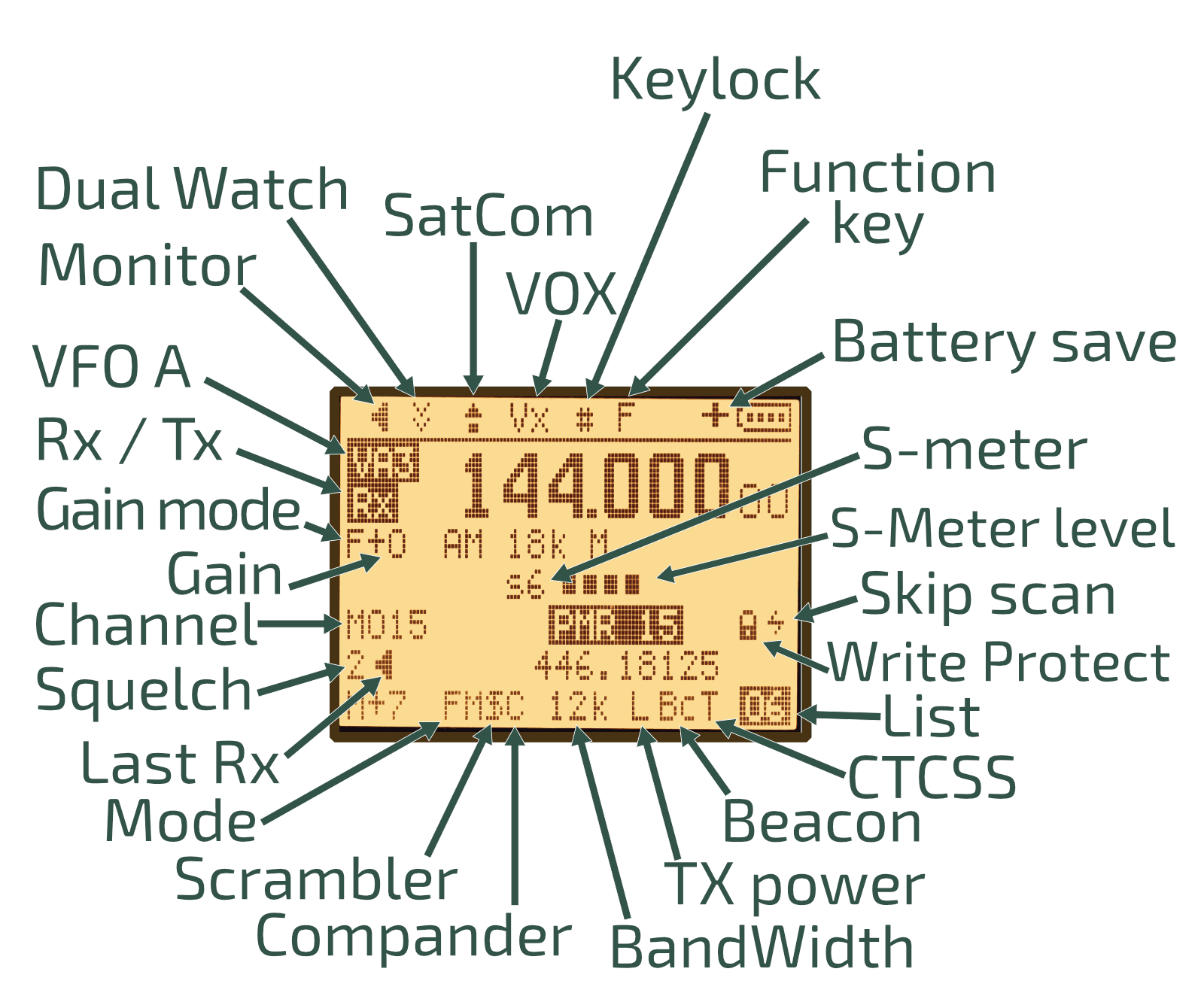
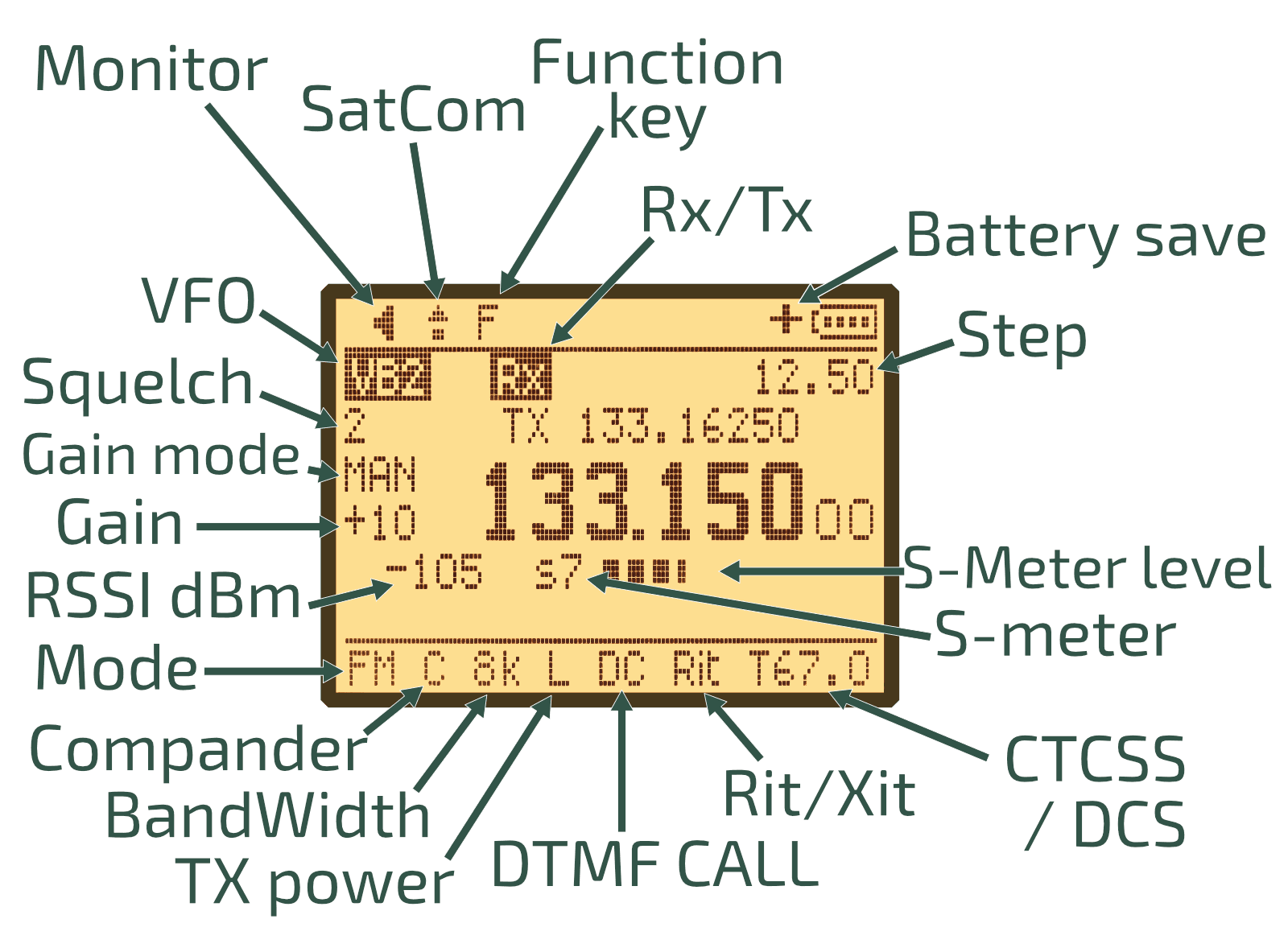
IJV allows you to view two channels simultaneously or dedicate the entire display to show information for just one:
| Dual visualization | Single visualization |
|---|---|
|
|
NOTE: In the VFO indicator, VA3 in the screenshot indicates VFO mode, line A of the display in the third band: F3 136∽173.9975 MHz.
Additional information can appear at the top of the screen or below the frequency:
| At the top of the screen. | Below the frequency. |
|---|---|

|

|
Meaning of the symbols:
| Symbol | Meaning |
|---|---|
| Monitor: The monitor mode has been enabled, the Squelch is open. | |
| DualRX(56): Dual reception on both channels has been enabled. | |
| Keylock: The walkie has the keypad locked. | |
| SatCom(52): Satellite reception mode has been enabled. | |
| BatSav(49): Indicates that power saving mode has been enabled. | |
| Skip Scan: Indicates that this channel will be skipped during a scan. | |
| Scramb(28): Indicates that scrambling has been enabled. | |
| Write Protect: The channel is protected against overwriting. This option is only configurable via CHIRP . Note: It is bugged and overwriting is allowed. |
Scan function:
IJV allows for three different types of scans.
Channel List:
- Assign channels to the list by pressing and holding 7(VOX).
- Select the list using
F+*(Scan). - Start the scan by pressing and holding
*Scan.Sm(Memory Scan) will appear at the top of the screen. When it reaches the last channel in the list, it will continue scanning from the beginning.
Frequency Band:
- Choose the band to scan by setting a frequency within the range or by selecting a Preset(54).
- Start the scan by pressing and holding
*Scan.SG(General Scan) will appear at the top of the screen. When it reaches the end of the band, it will continue scanning from the beginning.
Frequency Range:
- Set the starting frequency and press
F+Down Arrow. - Set the ending frequency and press
F+Up Arrow. - Start the scan by pressing and holding
*Scan.Sp(Partial Scan) will appear at the top of the screen. When it reaches the end of the range, it will continue scanning from the beginning.
| Channel list | Frequency band | Frequency range |
|---|---|---|
In all three cases, keep in mind that if you press:
- EXIT(D) while scanning, it will stop the scan and return to the initial frequency.
- EXIT(D) just as a signal is found, it will stop the scan and stay on that frequency.
- PTT will stop the scan at the last scanned frequency, not where it detected a signal.
*Scanwill add the frequency to the blacklist. It will appear with an * in the list of frequencies detected during the scan SCList(51).- Using the arrows, you can change the scan direction.
The SCList(51) is bugged. If the list of detected frequencies isn’t long enough to require scrolling, the last frequency won’t appear even though it’s saved. However, if you press the down arrow, you can see that it can be selected.
| Small list without scroll | Long list with scroll |
|---|---|
DTMF calls:
The basic idea is to have a set of walkie-talkies on the same frequency and be able to call one of them or a group of them using DTMF codes. Each walkie-talkie must have a unique identifier called Own ID(34) and have the D Call(41) + PTT ID(44): DTMF CALL ID enabled.
If we transmit on the channel without dialing the Own ID(34), nobody who has activated the D Call(41) + PTT ID(44): DTMF CALL ID will hear us. The green light will illuminate indicating radio signal reception, but no sound will be heard. However, if we mark an Own ID(34) that matches one of the walkie-talkies, it will directly hear the audio without having to “pick up”.
The configuration parameter D RSP(38) only apply to the receiving walkie-talkie:
- DO NOTHING: If the receiving walkie-talkie receives its Own ID(34), the audio will come out of the speaker. We could say it’s like a phone with automatic pick-up.
- RING: Behaves exactly like DO NOTHING but also emits a ringing tone that only stops when the receiver makes a transmission. I don’t see any usefulness in this.
- REPLY: Behaves exactly like DO NOTHING but the receiving walkie-talkie also replies. This way, the transmitting walkie-talkie knows that the other side is active and has heard the audio.
- BOTH: Enables both RING and REPLY.
If there is no longer transmission on the channel, the call will remain auto-picked up for the time configured in D Hold(39). If we want to delete a character in DTMF dial mode, we must press SideKey1.
There are several ways to make a call:
- Manually: Holding
PTT,Destination Own ID*Origin Own ID. For example, if our ID is 111 and we want to call 222, it would be: 222 * 111. - Semi-automatically: Pressing
*Scan,Destination Own ID,PTT. In this mode, our Own ID is also sent automatically. - Using UpCode(35): Configure the destination of the call in UpCode(35), whether it’s a walkie-talkie or a group ID.
To call a group, you need to define from
CHIRP
the parameter Settings -> DTMF/Selcall Settings -> DTMF Group Call Code, assuming it is #, calling 12# would be calling 120-129, with 1## to 100-199, ### 000-999 all possible users.
We must bear in mind that this is still an open channel; anyone can receive, and anyone can transmit on our frequency once a call is auto-accepted. That is, if a colleague calls a walkie-talkie, it opens communications, and if a third party unrelated to the group transmits on that frequency at that moment, the two “friendly” walkie-talkies will hear the third party, and of course, this third party has always been able to hear the audio from the “friendly” walkie-talkies.
I’ll leave a demonstrative video with configured DTMF contacts (equivalent to semi-automatic calling) and the D RSP(38) set to REPLY. We can see that IJV works without problems (unlike EGZUMER ) with the factory firmware.
| Stock firmware -> IJV | IJV -> Stock firmware | IJV -> IJV |
|---|---|---|
Frequency scanner:
This walkie-talkie has a very interesting function called Frequency Scanner F Copy(45). This allows us to determine the frequency and the
tone/code
being used by another walkie-talkie. All we need to do is activate this function and wait for the other walkie-talkie to emit a signal. Finally, we can save the configuration by pressing M(A). This feature is very useful when working with inexperienced people in the radio world who may not know what parameters are configured.
Another functionality related to the Frequency Scanner is the Tone/Code scanner CtScan(46). If we know the frequency at which the counterpart is transmitting but we don’t know its
tone/code
, we can use this functionality, and it will automatically detect the
tone/code
. Again, we can save the configuration by pressing M(A).
| Frequency scanner: F Copy(45) | Tone/Code scanner: CtScan(46) |
|---|---|
NOTE: The walkies shown in the videos have been configured with a tone as an example, but with digital codes, it would be exactly the same.
This firmware has a little-known option to start scanning for tones/codes from the menu itself: RxCTCS(8), Rx DCS(10). Just like before, we can save the configuration by pressing M(A). However, if it hasn’t detected the correct tones/codes , we can press the Up/Down arrow to continue scanning.
| Tones: RxCTCS(8) | Codes: Rx DCS(10) |
|---|---|
Frequencies above 1000 MHz (GHz):
To input frequencies higher than 1000 MHz, follow these steps:
- Switch to single-channel mode:
F+2(A/B). - Input the desired frequency by entering all 8 digits.
| |
Rit/Xit:
The Rit (Receiver Incremental Tuning) / Xit (Transmitter Incremental Tuning) allows for temporarily configuring a reception frequency different from the transmission frequency and vice versa. It essentially achieves the same outcome as setting an offset but in a quicker and more agile manner.
This functionality is particularly useful when communicating with equipment that isn’t perfectly aligned to the indicated frequency, emitting or receiving on frequencies slightly off from what their display shows. Some reasons for this could be the equipment’s poor precision or overheating due to excessive transmission time (Tx TOT).
Suppose we are communicating on the frequency 145.000 MHz, but the counterpart’s radio experiences a drift of +100 Hz on transmission and +200 Hz on reception.
In such a case, we need to configure our walkie-talkie with a reception frequency of 145.00010 MHz and a transmission frequency of 145.00020 MHz:
- Switch to single-channel mode:
F+2(A/B). - Input the desired frequency: 145.000 MHz.
- Set a Step(2) of 100Hz.
- Configure the Rit: Press and hold 8(R) and adjust using the arrows: 145.00010 MHz. You will see an ‘F’ at the top of the screen.
- Configure the Xit: Press and hold 8(R) and adjust using the arrows: 145.00020 MHz. You will see an ‘F’ at the top of the screen.
- After a while (8s) or upon transmitting, the ‘F’ at the top of the screen will disappear, and you will be able to receive with a 100Hz offset and transmit with a 200Hz offset.
- If the drift changes again, press the arrows to adjust both the reception and transmission frequencies simultaneously.
- Press Exit(D) to realign both frequencies to the starting point.
NOTE: To readjust the Rit/Xit, press ‘F’ to re-enable the function mode.
In the following videos, the configuration is performed using both the offset and the Rit/Xit, starting from single-channel mode, the initially configured frequency, and a 100Hz step. We can observe that using the offset required a total of 10 keystrokes, whereas using Rit/Xit only required 5:
| Offset | Rit/Xit |
|---|---|
Scrambling:
The conversations can be “encrypted” using scrambling Scramb(28), which is essentially a code used to encrypt the signal. The walkie-talkie that does not have it configured will hear a distorted version of the audio. We must remember that encrypting any communication is illegal in Spain.
We can observe its effect in this video:
CHIRP:
CHIRP is a widely used configuration software that supports a large number of devices.
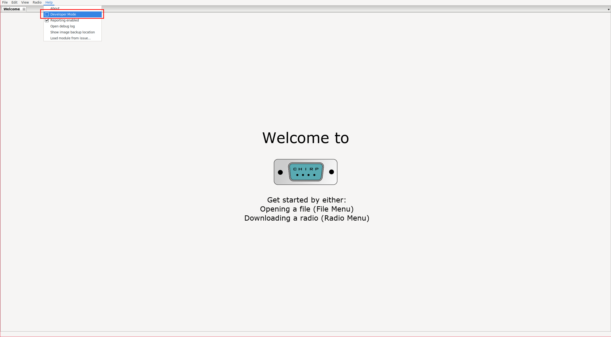
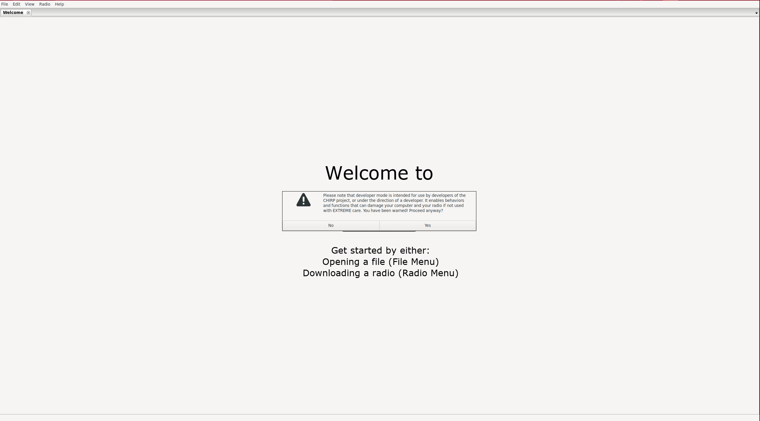
To manage the IJV firmware, we need to enable developer mode and load the Python module that came in the compressed file along with the firmware image.
Help -> 'Developer Mode
| Enable developer mode | Confirm |
|---|---|
|
|
It will ask us to restart CHIRP to apply the changes.
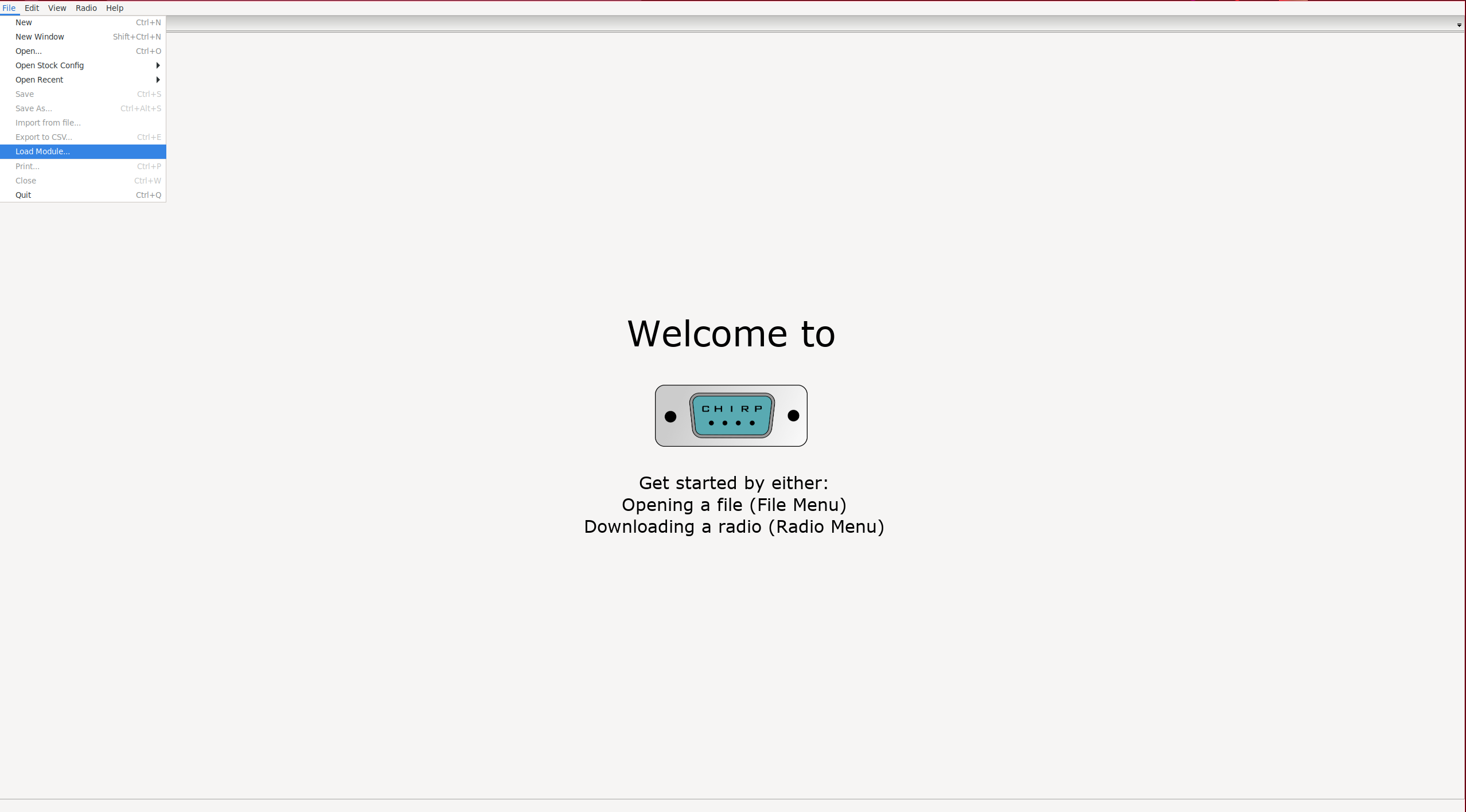
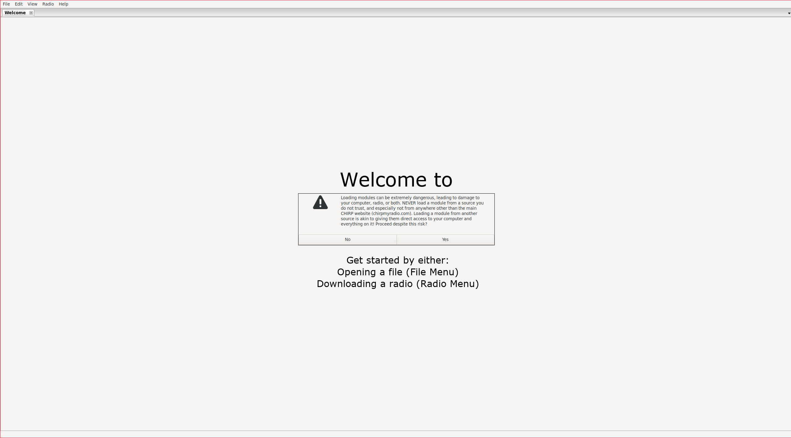
After restarting, load the module:
File -> Load Module...
| Load the module | Confirm |
|---|---|
|
|
Depending on whether we have made the hardware modification to have 999 channels, we load one version or another:
uvk5_IJV_v3_36.py
uvk5_IJV_vX3_36.py
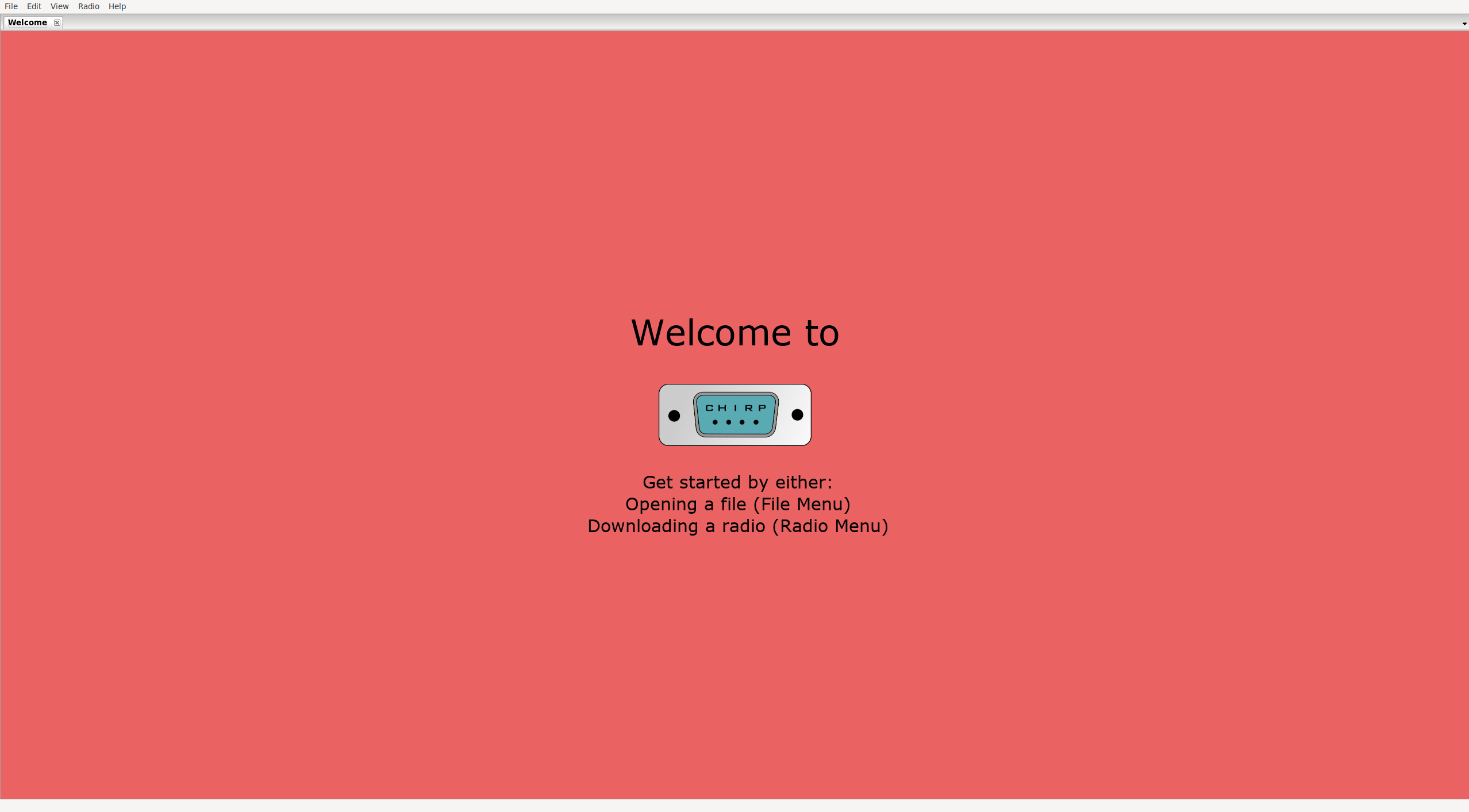
We will see that now the background of CHIRP has changed to red:
NOTE: CHIRP is a rather cumbersome software. For example, if we select a value from a dropdown menu but don’t remove the focus from the parameter, it will NOT be applied. This means that if we upload the configuration to the radio, it won’t have been applied.
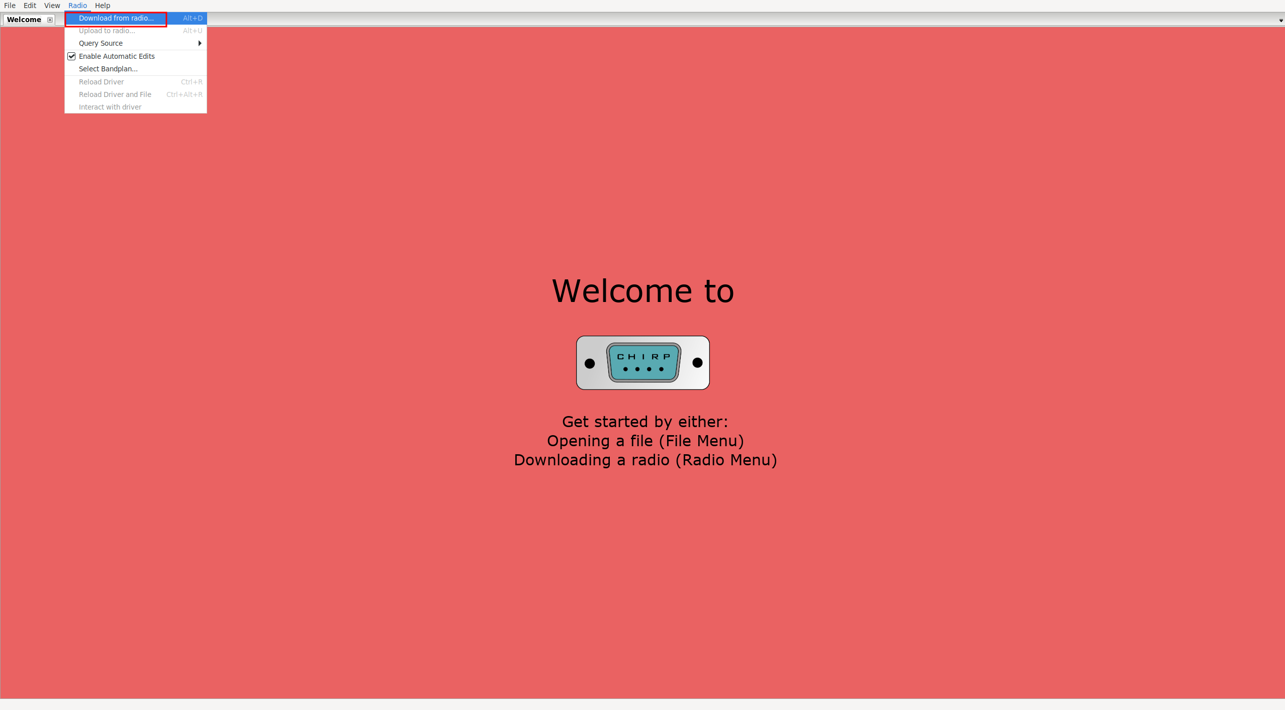
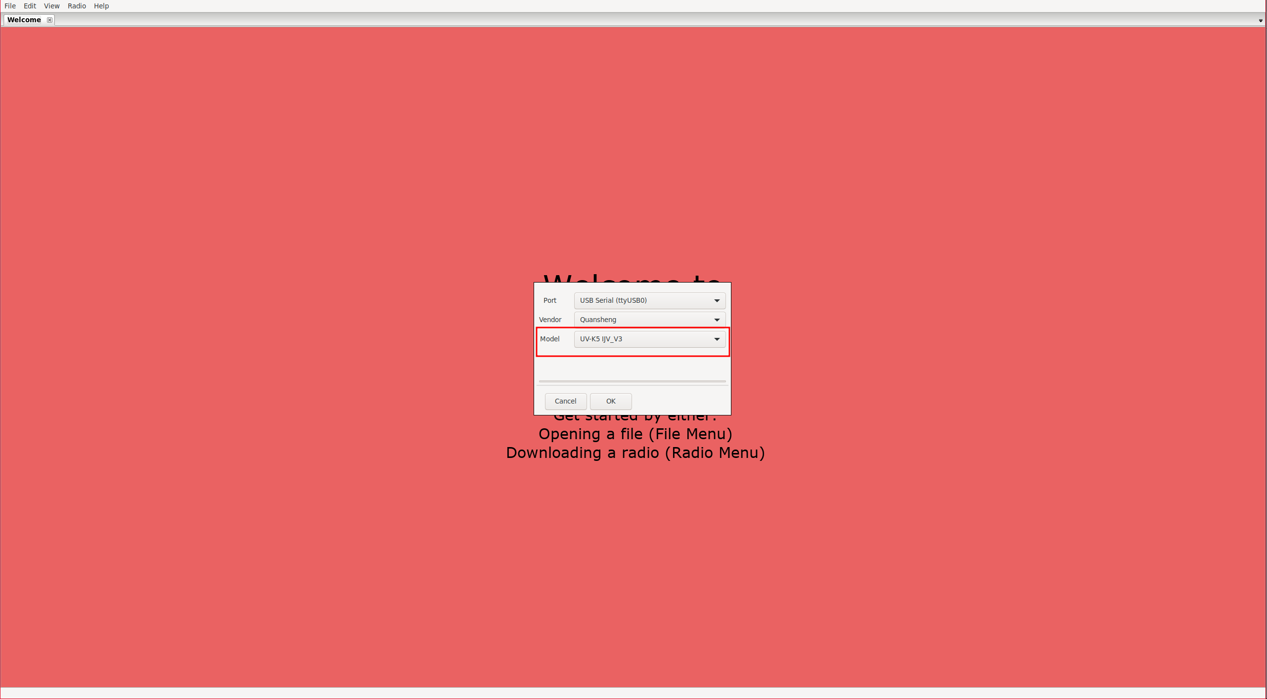
To connect to the radio:
Radio -> Download from radio
| Connect to the radio. | Select the model/firmware |
|---|---|
|
|
Channel list:
It will show us the channels. In my opinion, the interface leaves much to be desired as it is very complicated to understand what each field is for. It would have been much simpler to map one column for each option in the walkie-talkie menu as
CPS
does. Despite its lack of intuitiveness, I will try to explain what
each parameter
does:
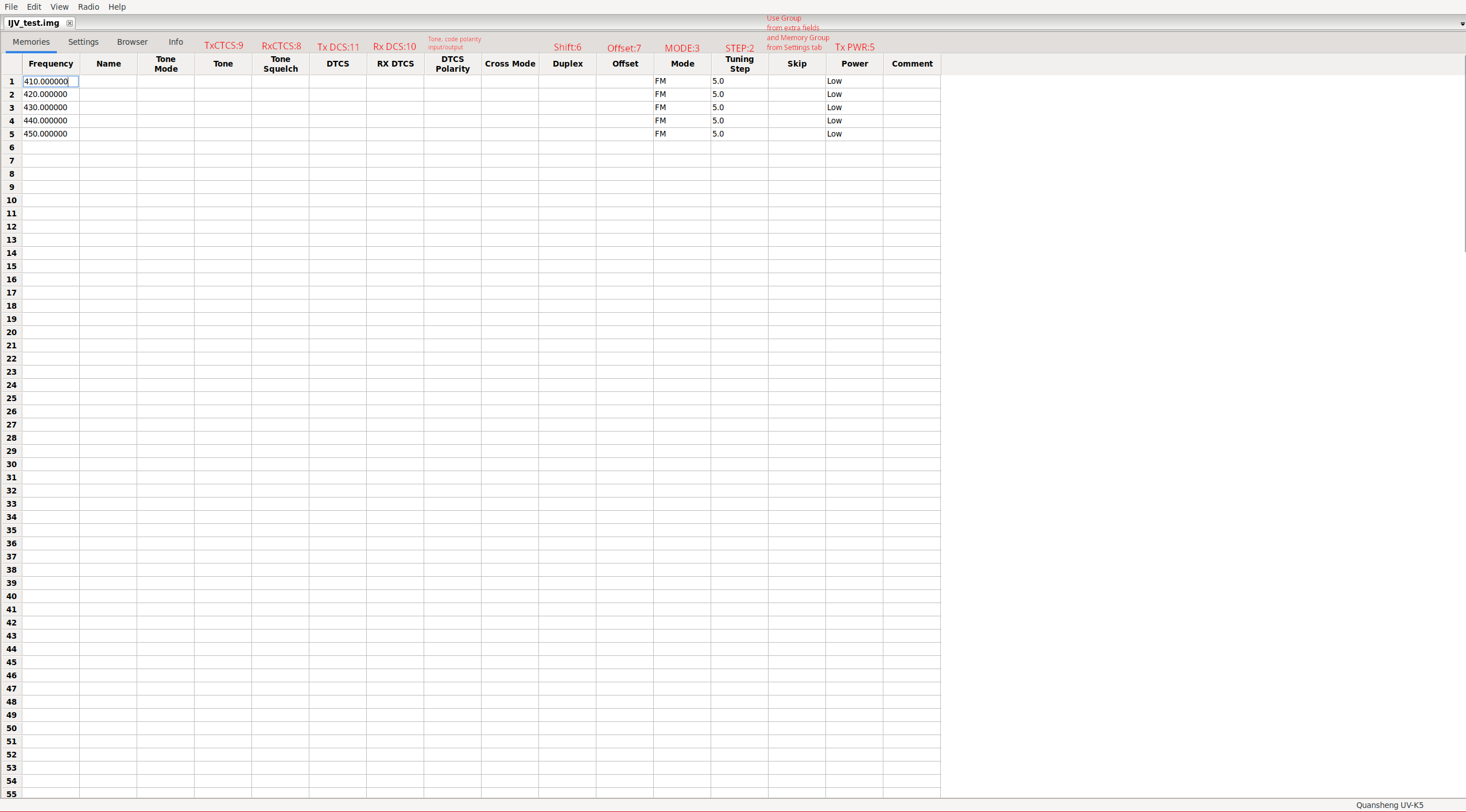
NOTE: The
Skip column
seems to be a bug because to ignore a channel in a scan, we only need to avoid it being part of a scanlist. To define the scanlists, we must do it from Settings -> Memory Group, and to make the channel part of one list or another, we must show the extra fields (explained below) and select the correct list in the column Group.
The DTCS Polarity option specifies the polarity of the tone/code for output/input. Tones only allow positive polarity (N), while digital codes allow positive (N) and negative (R) polarity:
| Value. | Output polarity. | Input polarity. |
|---|---|---|
| NN | Positive | Positive |
| NR | Positive | Negative |
| RN | Negative | Positive |
| RR | Negative | Negative |
The Tone Mode option can take one of the following values:
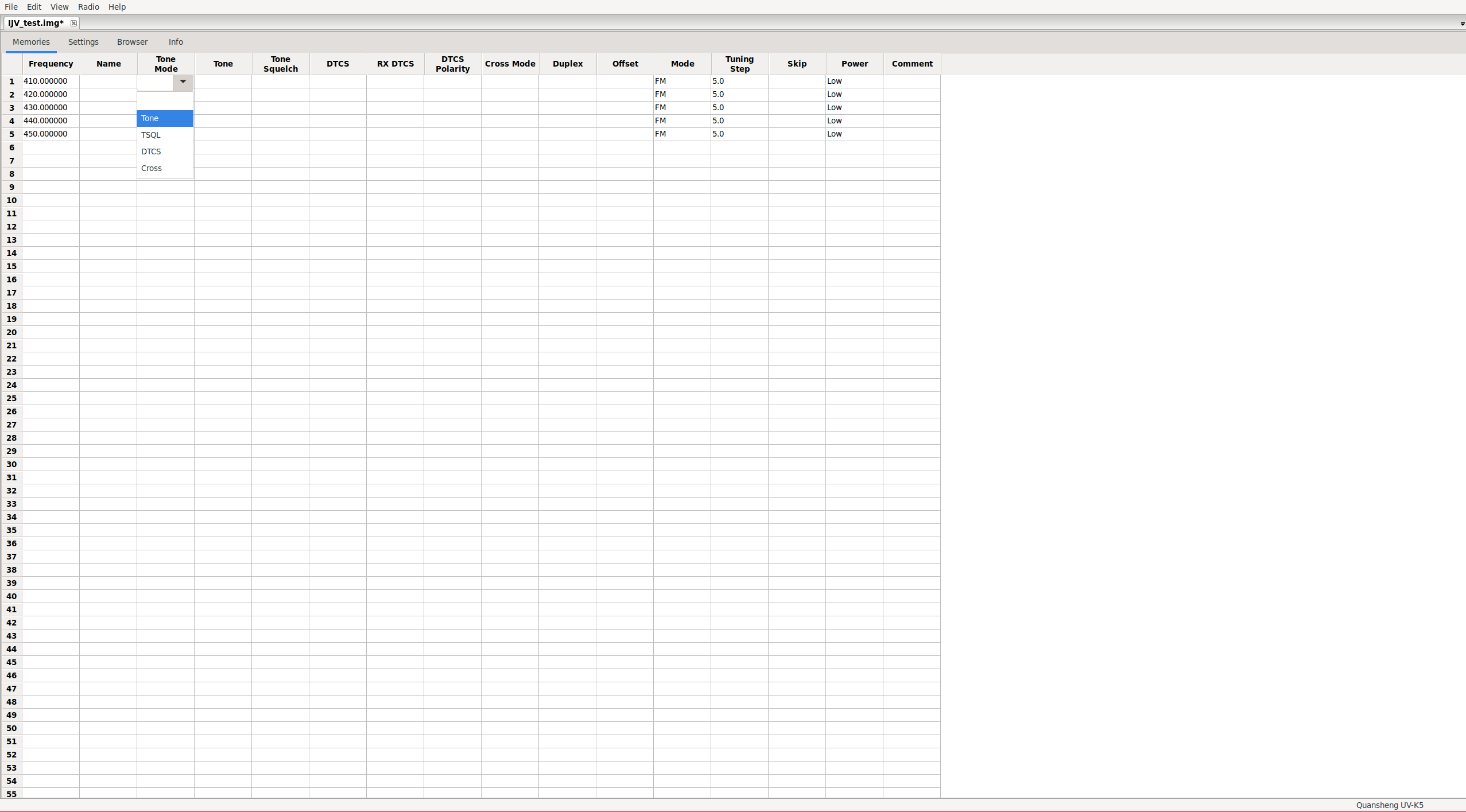
| Value. | Output Code/Tone. | Input Code/Tone. |
|---|---|---|
| None | No tone/code assigned | No tone/code assigned |
| Tone | Tone: Tone column | No tone/code assigned |
| TSQL | Tone: ToneSquelch column | Tone: ToneSquelch column |
| DTCS | Códe: DTCS column | Code: DTCS column |
| Cross | Mixed configuration. | Mixed configuration. |
NOTE: Cross, this mode should be assigned when we want to make mixed configurations, meaning not having only codes or only tones, but being able to choose for the input whether we will use codes or tones, and similarly for the output. This field depends on another column: Cross Mode.
The Cross Mode column determines whether codes or tones will be used. The first field indicates transmission and the second reception:
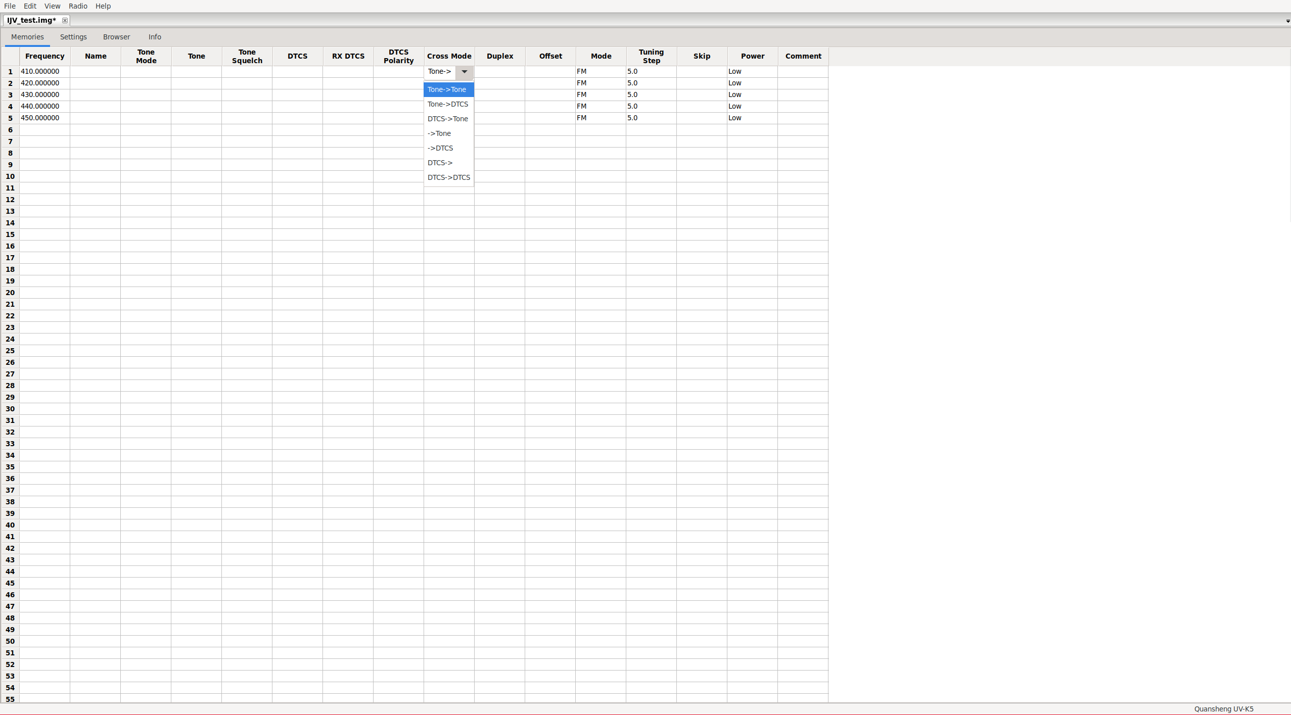
| Value. | Output Code/Tone. | Input Code/Tone. |
|---|---|---|
| Tone -> Tone | Tone: Tone column | Tone: ToneSquelch column |
| Tone -> DTCS | Tone: Tone column | Code: RX_DTCS column |
| DTCS -> Tone | Code: DTCS column | Tone: ToneSquelch column |
| -> Tone | No tone/code assigned | Tone: ToneSquelch column |
| -> DTCS | No tone/code assigned | Code: RX_DTCS column |
| DTCS -> | Code: DTCS column | No tone/code assigned |
| DTCS -> DTCS | Code: DTCS column | Code: RX_DTCS column |
NOTE: For some reason, the option Tone -> is missing. This is a CHIRP issue, and I suppose they will fix these kinds of bugs over time. Remember that support for Quansheng is still experimental.
Some modes are more restrictive than others. For example, if we configure only digital code as output, it doesn’t make sense to have an input tone configured. CHIRP detects these restrictions but doesn’t do it very well. We have to click on other fields, even if we’re not changing anything, to apply these restrictions.
Settings:
In the Settings tab, we can find the bulk of the configuration options.
Basic Settings:
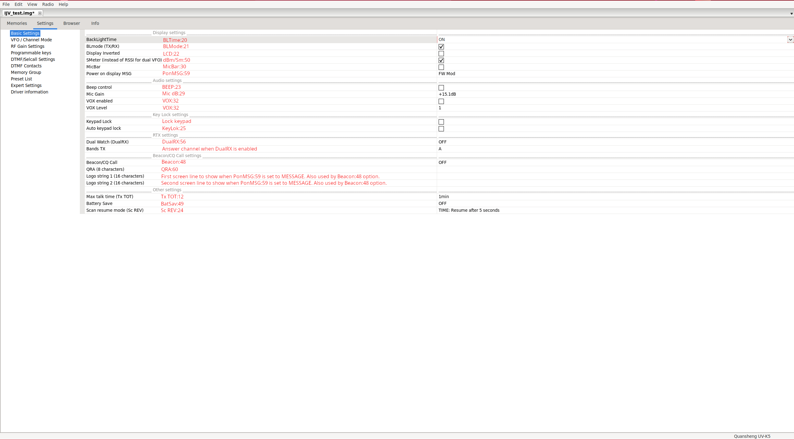
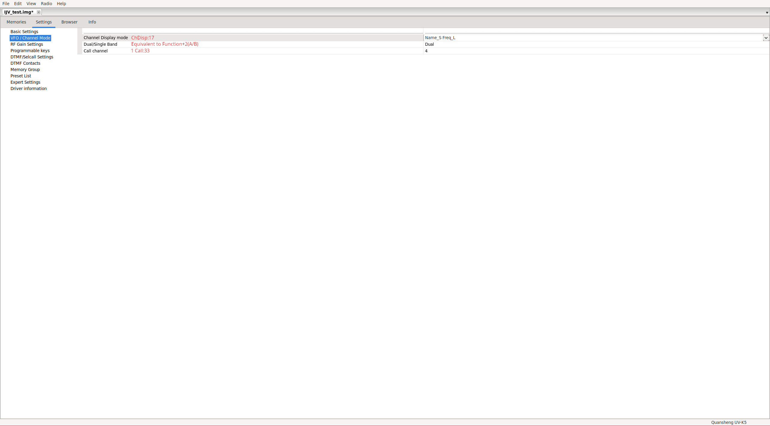
VFO/Channel Mode:
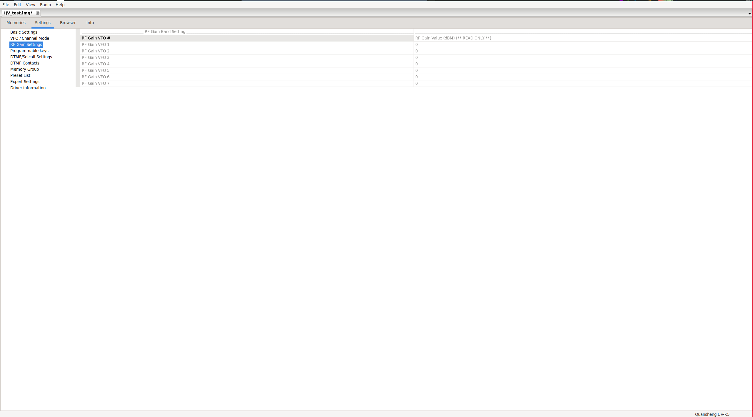
RF Gain Settings:
This section only allows us to read the gain applied in reception on each band.
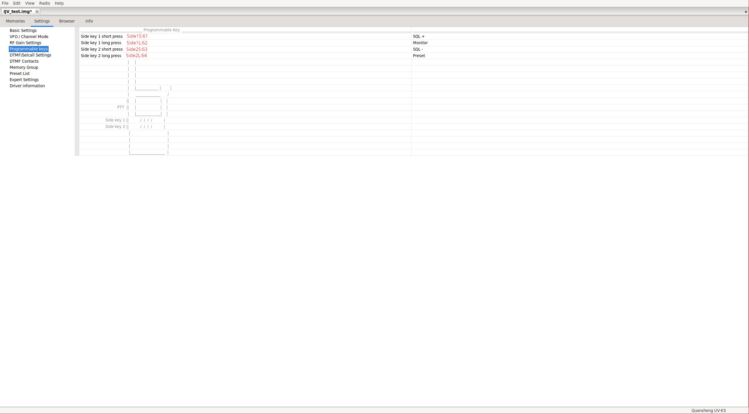
Programmable keys:
This section allows configuring the function of the side keys.
DTMF/Selcall Settings:
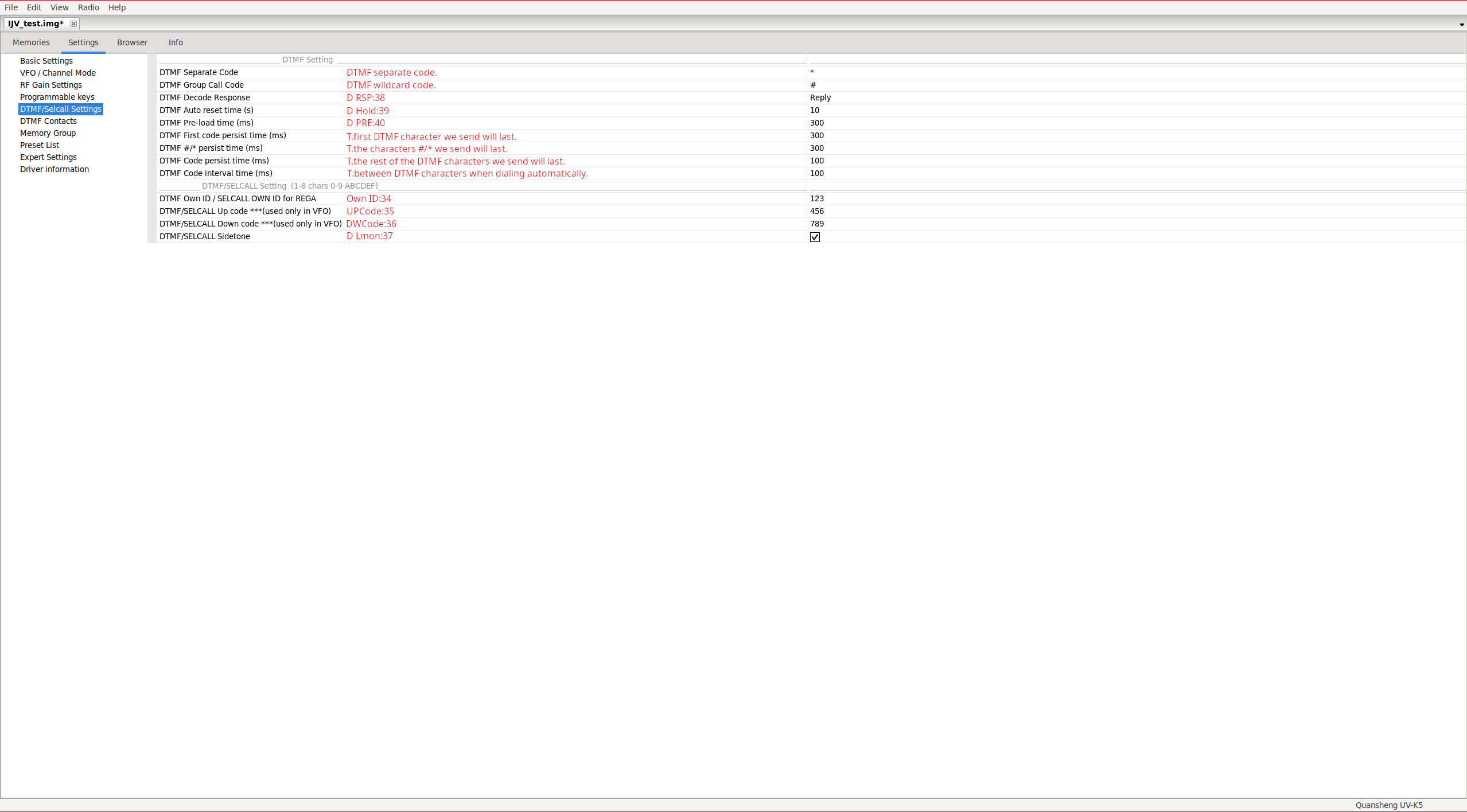
DTMF Contacts:
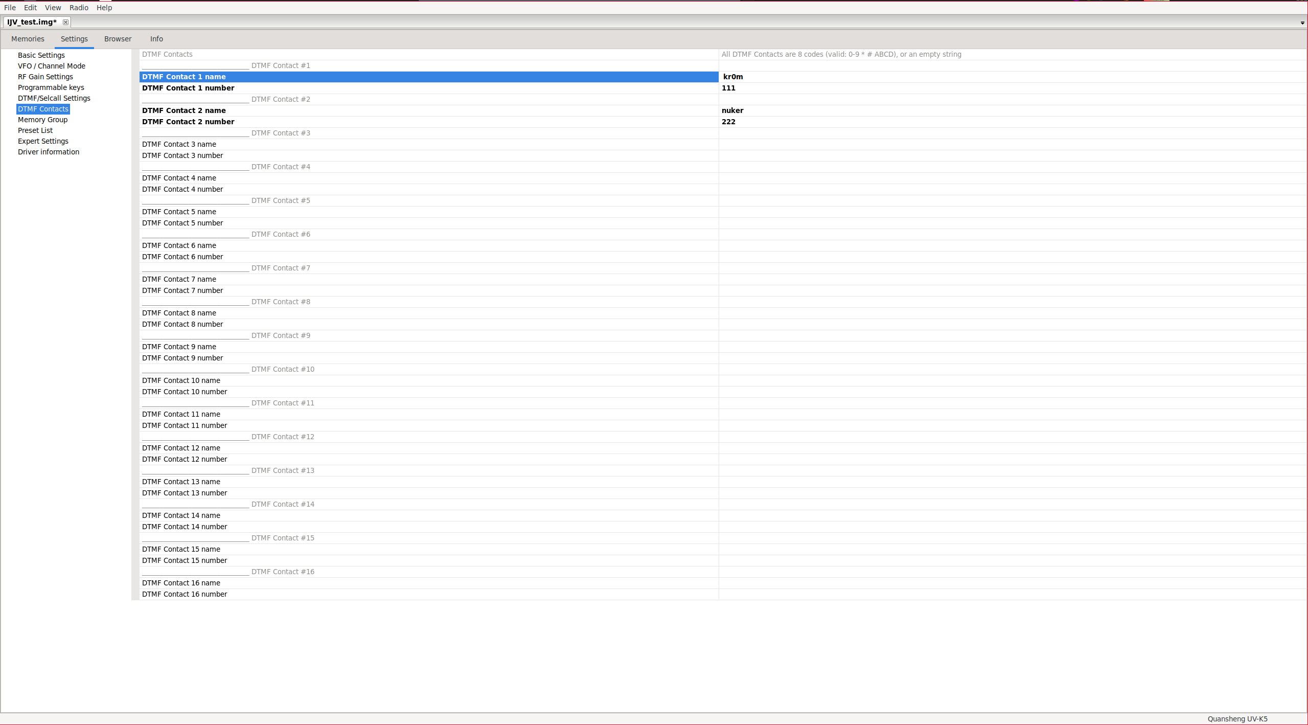
Editing DTMF contacts.
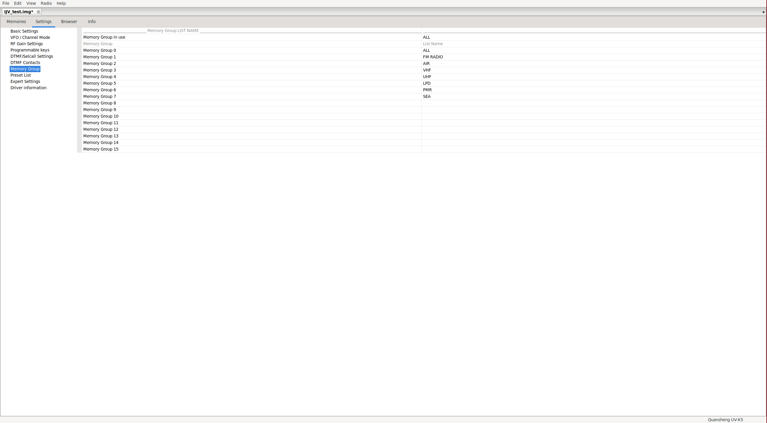
Memory Group:
Configuration of the active scan list and editing of the list names.
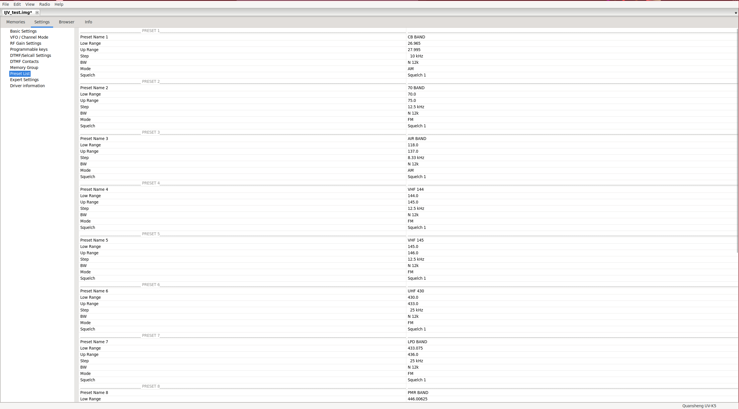
Preset list:
In this section, we can edit the frequency range that each band covers and the default parameters for each one. This is what IJV calls a preset: PrSave(19)/Preset(54).
Expert Settings:
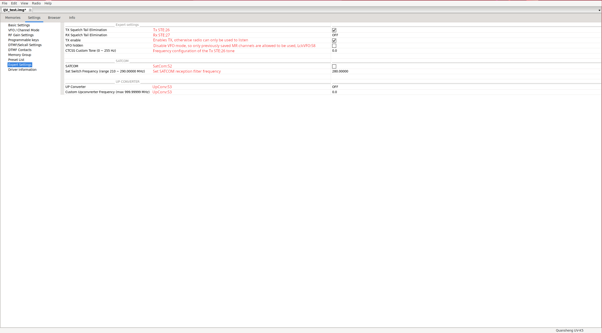
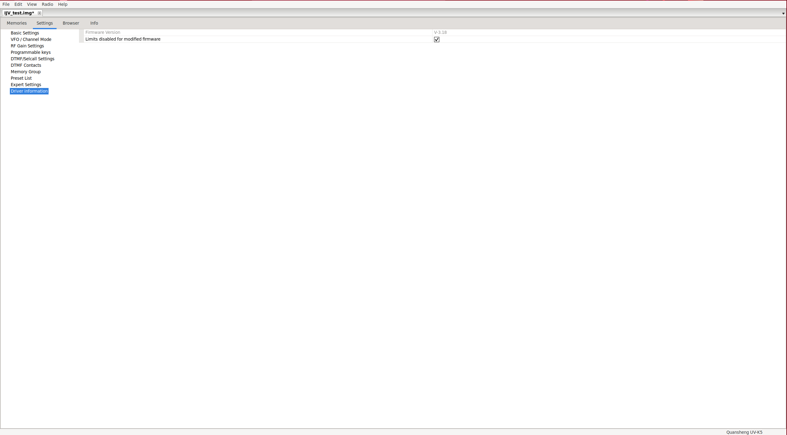
Driver information:
In this section, we can view the firmware version and disable the default limits imposed by CHIRP. Disabling these limits is necessary when using IJV.
Browser:
This section appears to be a raw configuration parameter explorer. Normally, there is no need to modify anything from this section.

Info:
This tab is purely informational, displaying different types of information in each section.
Features:
It shows the radio’s capabilities:

Image Metadata:
It seems like it’s bugged or this radio doesn’t provide that information.
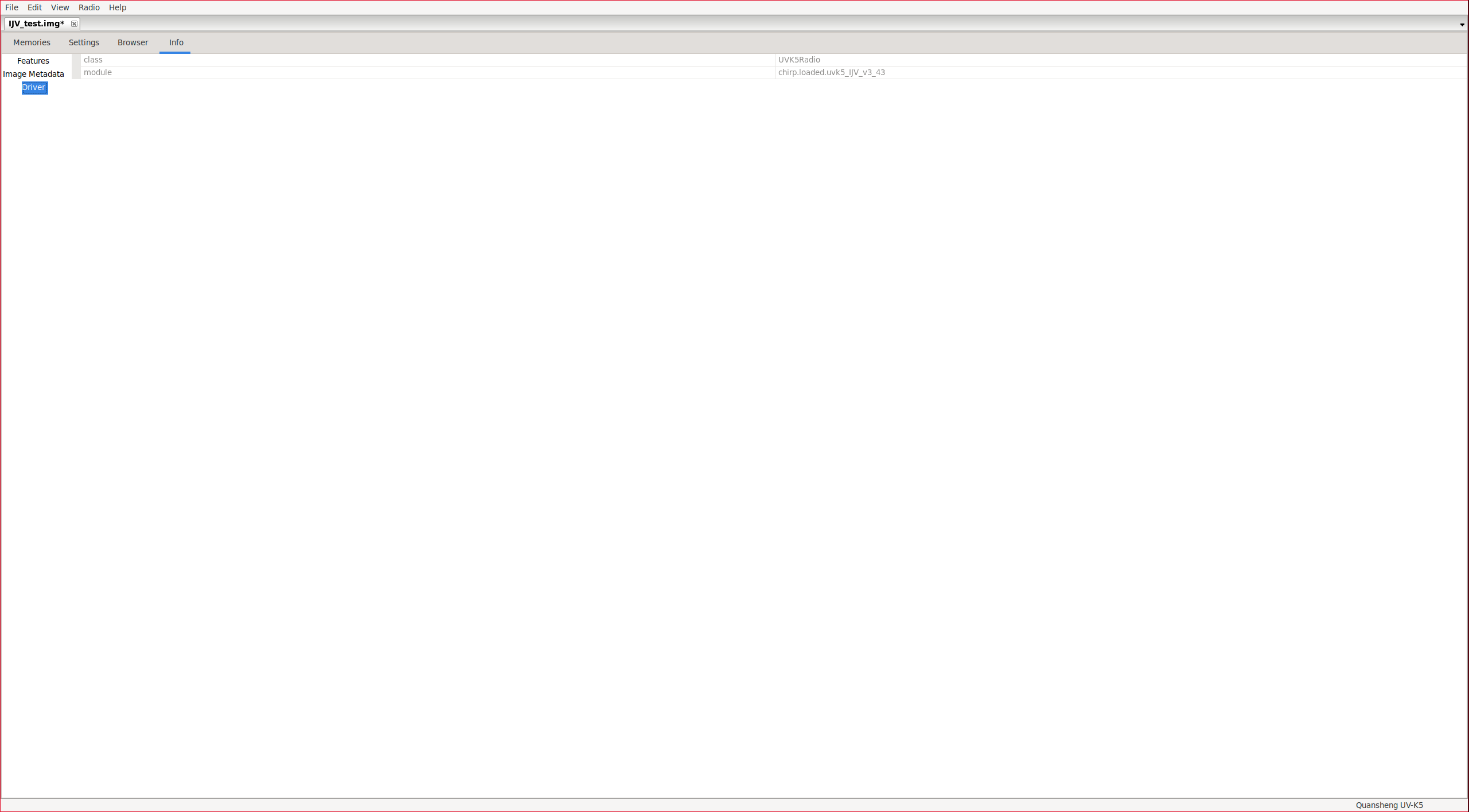
Driver:
It shows information about the radio model and the module loaded in CHIRP.
Extra fields:
In the “Memories” section, additional parameters can be displayed if we enable them.
View -> Show extra fields
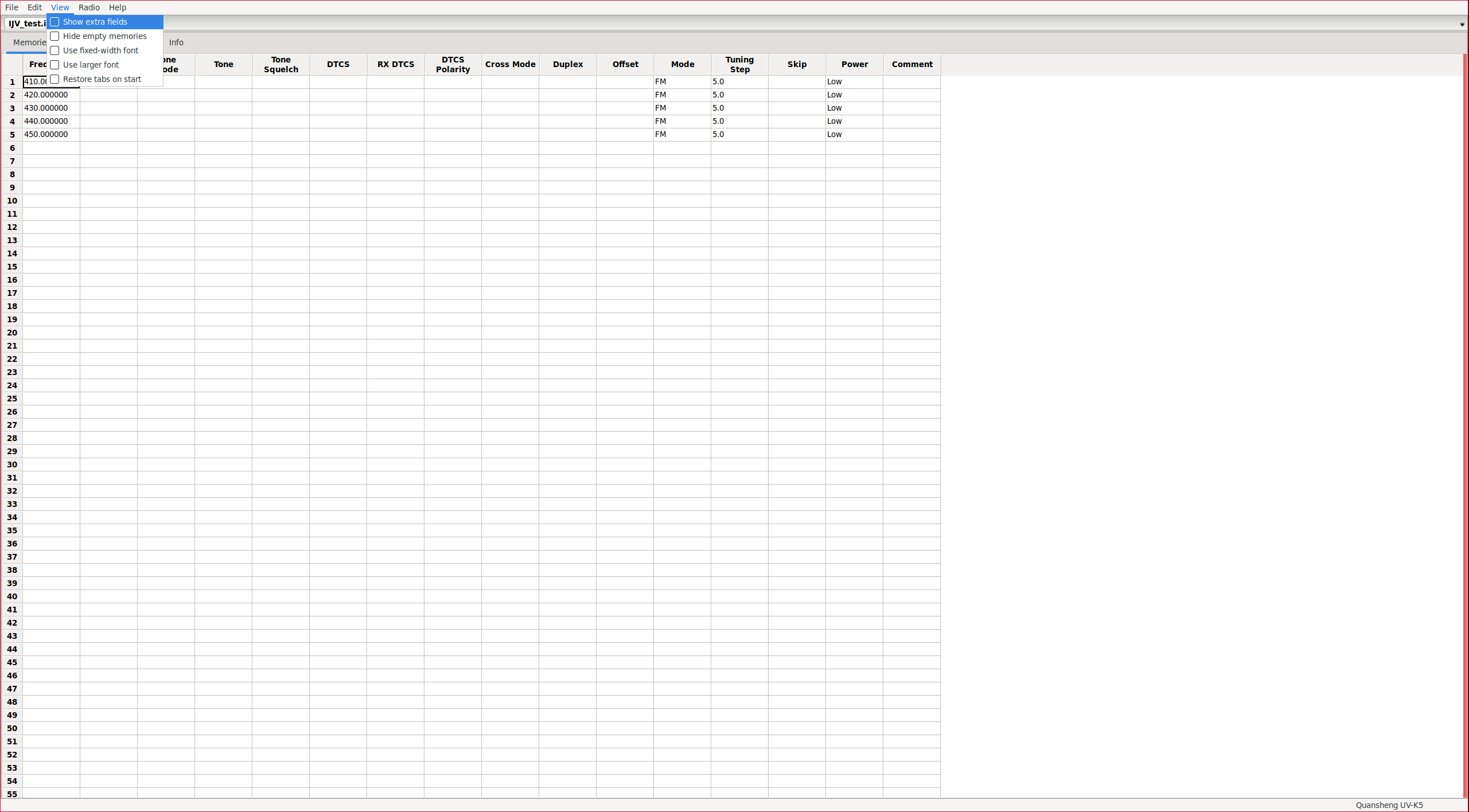
|
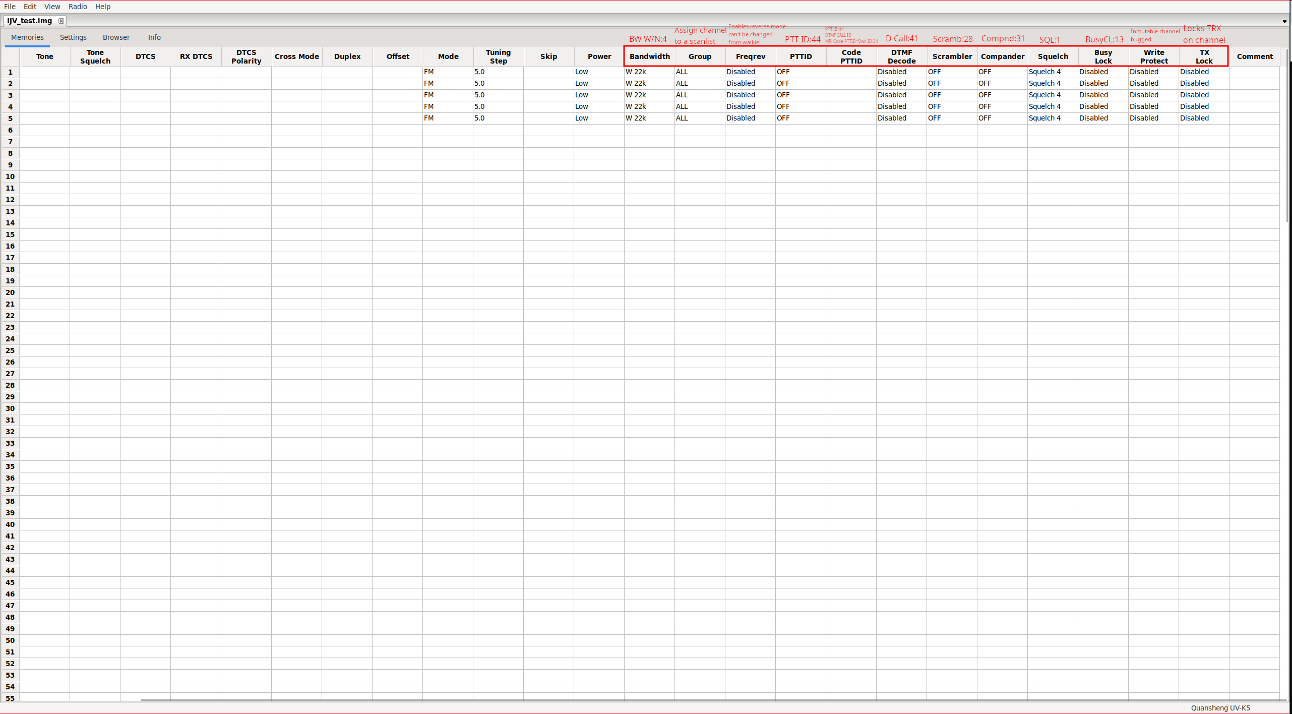
|
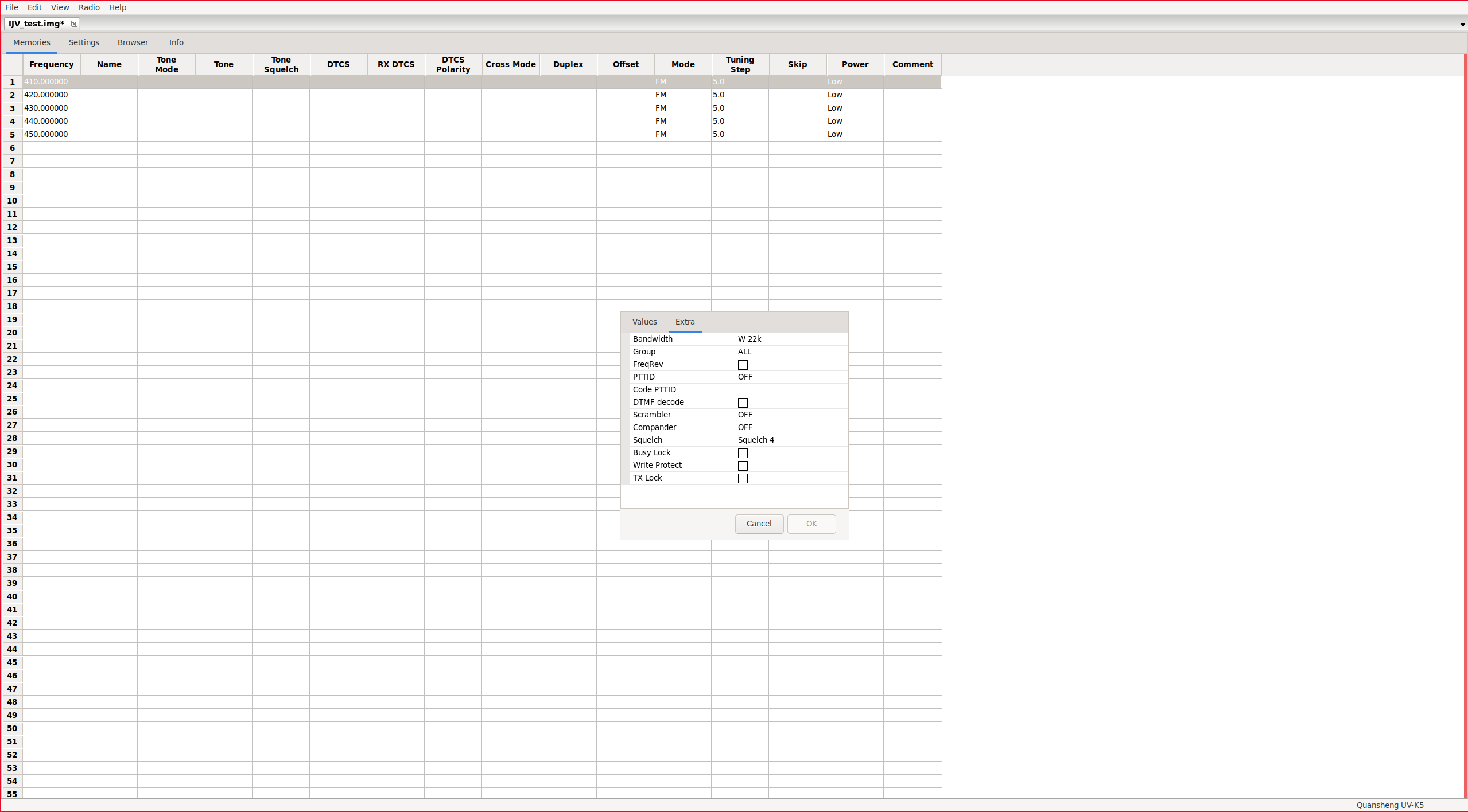
NOTE: The “Write Protect” option is bugged; it still allows overwriting protected channels.
Actually, these parameters can also be accessed without enabling the mentioned menu. You just need to click on:
Right click over the channel -> Properties -> Extra Tab
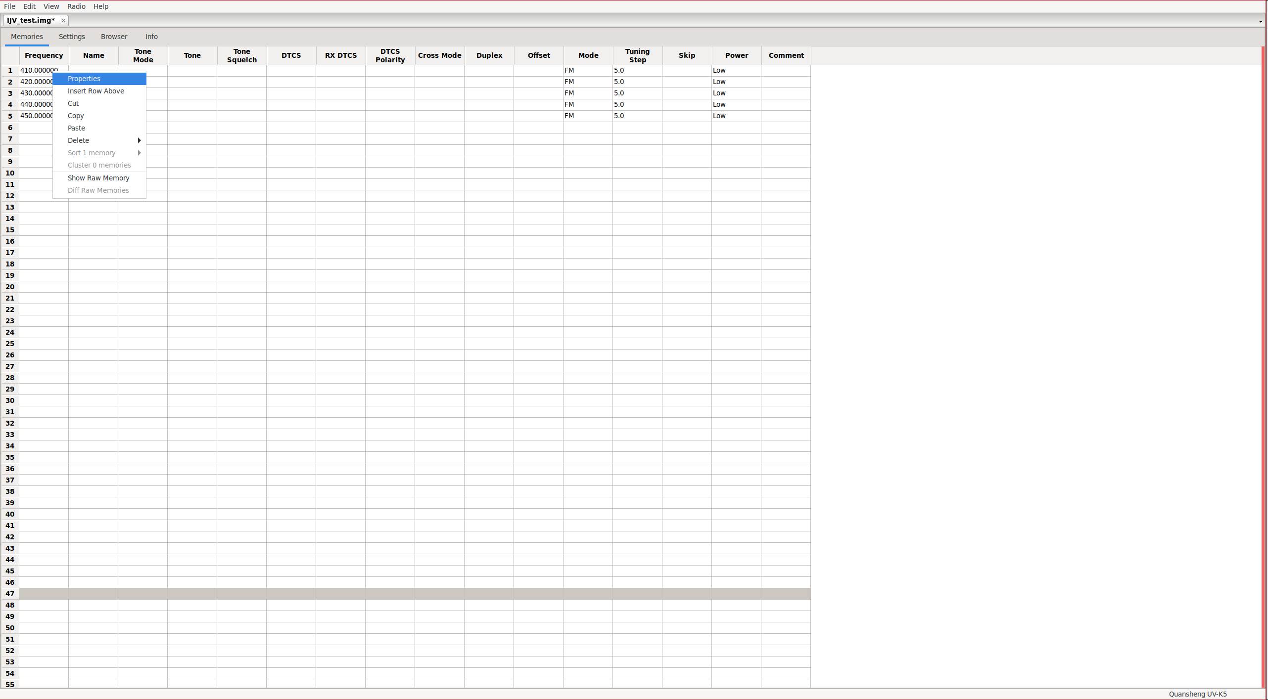
|
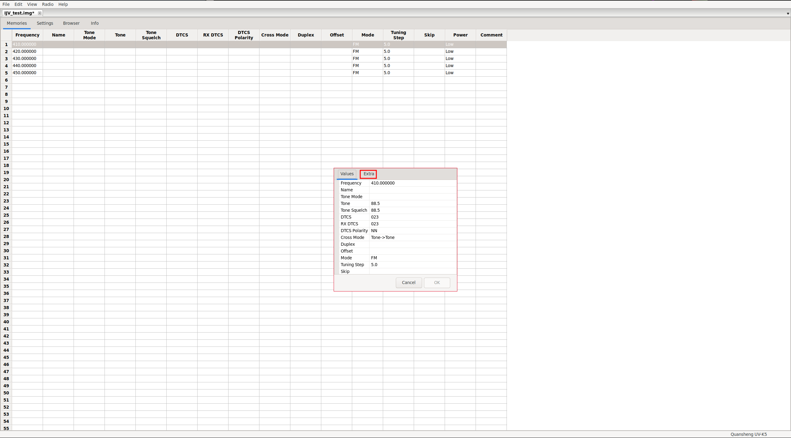
|
|
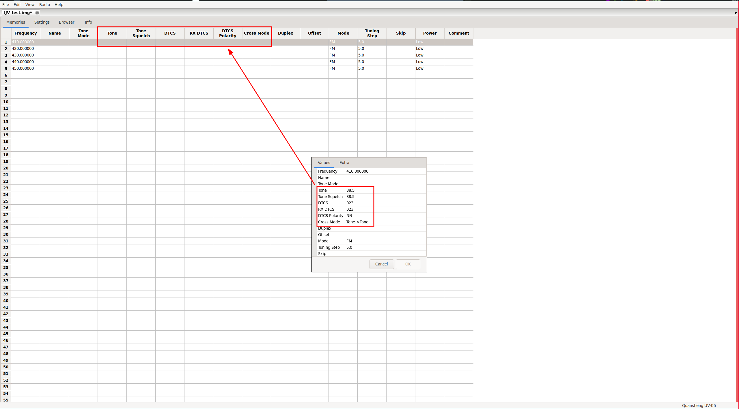
It seems that CHIRP is quite buggy at the moment, at least with this walkie model. For example, we can see on channel 1 that it doesn’t have any
tone/code
assigned. But in the Properties section, it shows digital tones and other settings.
BUGS:
- The SCList(51) list is bugged, as demonstrated in the video of the scan function section.
- Write Protect option in CHIRP : The channel protected against overwriting can indeed be overwritten.


