An interrupt request is a signal to indicate to the processor that something requires its immediate attention. These requests can be generated by both hardware devices (IRQ) and programs, and even under special circumstances (usually errors) by the processor itself.
Before we begin, it is recommended that you read these previous articles:
- Boot Sector
- Interrupts
- Memory
- Stack
- IF-ELSE
- Functions
- Memory Segmentation
- Reading Data from Disk
- Entering Protected Mode 32bits
- Compilation, Linking, Stack Management, and Variables in C
- Pointers
- Kernel
- EntryPoint
- Gmake
- Gmake wildcards
- I/O Hardware
- Cross Compiler
- Video Driver
Without interrupts, the CPU would have to constantly check the devices to verify their activity. Interrupts allow devices to remain silent until they require attention from the processor.
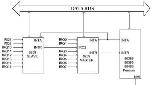
Hardware devices communicate their interrupts through lines on the control bus, each of these lines is called an IRQ. These lines reach the Programmable Interrupt Controller (PIC), which queues and prioritizes the interrupts before communicating them to the CPU.
These IRQs are limited, with a total of 16 (0-15). This is because we have two PICs, each with 8 IRQs, but it’s important to note that they are connected in cascade. The PIC closest to the CPU is the MASTER, and the one furthest away is the SLAVE. The connection between the MASTER (IRQ2) and the SLAVE (IRQ9) consumes one IRQ on each PIC.
When a hardware interrupt occurs, the following steps are followed:
- The MASTER PIC notifies the CPU that there are pending interrupts through a physical track called INTR (Interrupt Request).
- When the CPU receives the interrupt, it responds to the PIC through a physical track called INTA (Interrupt Acknowledge). The CPU sends this signal twice, once as a notification and another to instruct the PIC to place the interrupt ID on the data bus.
- The corresponding PIC writes the interrupt ID to the data bus.
- The CPU reads it and uses this ID to locate the Interrupt Service Routine (ISR) associated with that interrupt.
- The CPU completes the instruction it is executing.
- The CPU saves the contents of the registers.
- The CPU disables the interrupt system.
- The CPU executes the service routine.
- Once the service routine has been executed, the CPU notifies the corresponding PIC with an EOI (End Of Interrupt) signal.
- The CPU re-enables the interrupt system.
- It ends with an IRET (Interrupt Return) instruction that restores the contents of the registers: CS, EIP, EFLAGS, SS, ESP.
The aforementioned service routine is located by consulting the Interrupt Descriptor Table (IDT). This table simply relates the interrupt ID to the memory position of the ISR. The codes range from 0 to 255. If an interrupt occurs and there is no entry in the IDT for that interrupt, the processor will enter panic mode and restart.
NOTE: In 16-bit real mode, the IDT is called the IVT (interrupt vector table).
Not all interrupts have to be hardware-related.
- Hardware interrupt: These occur when a device needs attention from the processor and generates an electrical signal on the assigned IRQ line. This signal is collected and processed by the PIC (Programmable Interrupt Controller) before being sent to the processor.
- Maskable interrupt: Under software control, the processor can accept or ignore the interrupt signal. When the processor receives one of these interrupts, it responds with an INTA (interrupt acknowledge) to the PIC and looks for the associated service routine for that interrupt.
- Non-maskable interrupt: This means that the interrupt cannot be disabled by software. These types of interrupts occur when a signal is received on the NMI (Nonmaskable Interrupt) pin of the processor. They are reserved for critical cases, such as when a parity error is detected in memory. Additionally, they have higher priority than maskable interrupts.
When the processor receives one of these interrupts, no INTA is generated, and the processor assigns it a 2 as the exception ID.
- Software interrupts: These allow software to generate any of the 256 types of maskable interrupts. The process followed is exactly the same as when a hardware interrupt is received on the INTR pin, except in this case, the interrupt ID is known, and no INTA is required.
- Processor exceptions: During the operation of the processor, exceptional circumstances can occur, such as a division by zero. In these cases, the processor generates an exception that is treated as if it were a software interrupt, with the difference that the interrupt ID depends on the type of exception.
Exceptions follow a priority order:
- Processor exceptions
- Software interrupts
- Non-maskable hardware interrupts
- Maskable hardware interrupts
In the following table, we can see the relationship between interrupts and their assigned IRQs as loaded by the default BIOS configuration:
Master 8259:
IVT | INT # | IRQ # | Description
-----------+-------+-------+------------------------------
0x0020     | 0x08  | 0     | PIT
0x0024     | 0x09  | 1     | Keyboard
0x0028     | 0x0A  | 2     | 8259A slave controller
0x002C     | 0x0B  | 3     | COM2 / COM4
0x0030     | 0x0C  | 4     | COM1 / COM3
0x0034     | 0x0D  | 5     | LPT2
0x0038     | 0x0E  | 6     | Floppy controller
0x003C     | 0x0F  | 7     | LPT1
Slave 8259:
IVT | INT # | IRQ # | Description
-----------+-------+-------+------------------------------
0x01C0     | 0x70  | 8     | RTC
0x01C4     | 0x71  | 9     | Unassigned
0x01C8     | 0x72  | 10    | Unassigned
0x01CC     | 0x73  | 11    | Unassigned
0x01D0     | 0x74  | 12    | Mouse controller
0x01D4     | 0x75  | 13    | Math coprocessor
0x01D8     | 0x76  | 14    | Hard disk controller 1
0x01DC     | 0x77  | 15    | Hard disk controller 2
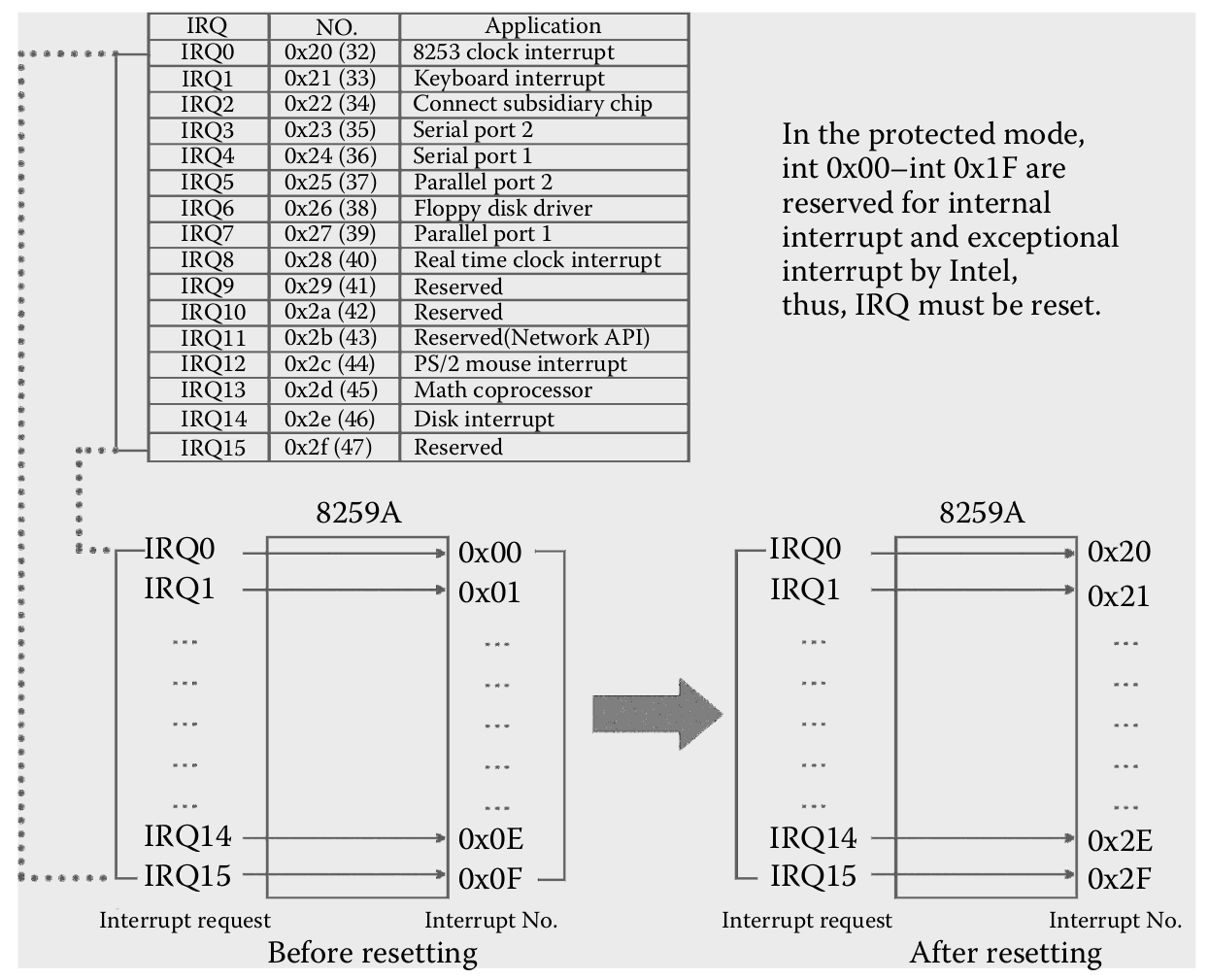
When entering protected mode, the CPU itself will use codes 0x0 - 0x1F for internal interrupts, creating an overlap (Intel bug). Therefore, we will need to remap the original interrupts to other codes.
List of interrupts in protected mode:
IVT | INT #     | Description
-----------+-----------+-----------------------------------
0x0000     | 0x00      | Divide by 0
0x0004     | 0x01      | Reserved
0x0008     | 0x02      | NMI Interrupt
0x000C     | 0x03      | Breakpoint (INT3)
0x0010     | 0x04      | Overflow (INTO)
0x0014     | 0x05      | Bounds range exceeded (BOUND)
0x0018     | 0x06      | Invalid opcode (UD2)
0x001C     | 0x07      | Device not available (WAIT/FWAIT)
0x0020     | 0x08      | Double fault
0x0024     | 0x09      | Coprocessor segment overrun
0x0028     | 0x0A      | Invalid TSS
0x002C     | 0x0B      | Segment not present
0x0030     | 0x0C      | Stack-segment fault
0x0034     | 0x0D      | General protection fault
0x0038     | 0x0E      | Page fault
0x003C     | 0x0F      | Reserved
0x0040     | 0x10      | x87 FPU error
0x0044     | 0x11      | Alignment check
0x0048     | 0x12      | Machine check
0x004C     | 0x13      | SIMD Floating-Point Exception
0x00xx     | 0x14-0x1F | Reserved
0x0xxx     | 0x20-0xFF | User definable(32-255)
The conflicting codes are:
0x0020     | 0x08  | 0     | PIT
0x0024     | 0x09  | 1     | Keyboard
0x0028     | 0x0A  | 2     | 8259A slave controller
0x002C     | 0x0B  | 3     | COM2 / COM4
0x0030     | 0x0C  | 4     | COM1 / COM3
0x0034     | 0x0D  | 5     | LPT2
0x0038     | 0x0E  | 6     | Floppy controller
0x003C     | 0x0F  | 7     | LPT1
0x0020     | 0x08      | Double fault
0x0024     | 0x09      | Coprocessor segment overrun
0x0028     | 0x0A      | Invalid TSS
0x002C     | 0x0B      | Segment not present
0x0030     | 0x0C      | Stack-segment fault
0x0034     | 0x0D      | General protection fault
0x0038     | 0x0E      | Page fault
0x003C     | 0x0F      | Reserved
We can see the complete list of interrupts on this website:
https://dos4gw.org/Interrupts_-_List
The protected mode interrupts cover the interrupt IDs 0x00-0x1F (0-31), so the range 0x20-0x1F (32-255) is available. It is within this range that we will remap the original interrupts of the PICs.
After remapping, it will look like this:
The reprogramming of the PICs will be done through the I/O-ports registers:
0x20: Port de control del MASTER
0x21: Port de datos del MASTER
0xA0: Port de control del SLAVE
0xA1: Port de datos del SLAVE
The PICs accept two types of commands: the ICW (Initialization Command Word) that initializes them, and the OCW (Operation Command Word) that allows programming the operating mode. We will only use the ICW.
Before the PICs in a system start working, they must receive a sequence of ICWs that initialize them. The PIC expects to receive these commands sequentially, one after another. The first three are mandatory, while ICW4 is optional.
ICW1 is composed of the sum of two values:
- 10: Indicates that it is the first ICW1 command
- 0/1: Indicates whether an ICW4 will be sent
In our case, we will send an ICW4, so we start the reprogramming with 0x11. This command makes the PIC wait for 3 more commands in the data port:
- Vector offset ICW2: Indicates the initial interrupt ID to start mapping the IRQs. By default, it is PIC-M: 0x08, so ID 0x08 is assigned to IRQ0, 0x09 to IRQ1, and so on. The same reasoning applies to PIC-S, with 0x70-IRQ8, 0x71-IRQ9, and so on.
- Mode in which the two PICs are connected (IRQ2-IRQ9) ICW3
- CPU we are working on ICW4 (0:8085/1:8086)
NOTE: Let’s remember that PIC-M covers IRQs 0-7 and PIC-S covers 8-15. This detail is important when indicating how the PICs are connected to each other.
In addition to the remapping, we will also mask the interrupts to later unmask the ones we are interested in.
The remapping and masking code in C would be as follows.
void remap_irqs();
void mask_irq(unsigned char IRQline);
void unmask_irq(unsigned char IRQline);
#include "irqs.h"
#include "../drivers/ports.h"

void remap_irqs() {
    port_byte_out(0x20, 0x11); // Reprogramming command PIC-M
    port_byte_out(0xA0, 0x11); // Reprogramming command PIC-S

    port_byte_out(0x21, 0x20); // vector offset PIC-M to 0x20 (32 decimal)
    port_byte_out(0xA1, 0x28); // vector offset PIC-S to 0x28 (40 decimal)

    port_byte_out(0x21, 0x04); // PIC-S at IRQ2 (0000 0100)
    port_byte_out(0xA1, 0x02); // PIC-M at IRQ9 (0000 0010)

    port_byte_out(0x21, 0x01); // 8086 CPU PIC-M
    port_byte_out(0xA1, 0x01); // 8086 CPU PIC-S

    port_byte_out(0x21, 0xFF); // disable all IRQs on PIC-M
    port_byte_out(0xA1, 0xFF); // disable all IRQs on PIC-S

    //port_byte_out(0x21, 0x00); // enable all IRQs on PIC-M
    //port_byte_out(0xA1, 0x00); // enable all IRQs on PIC-S
}

void mask_irq(unsigned char IRQline) {
    unsigned short port;
    unsigned char value;

    if(IRQline < 8) {
        port = 0x21;
    } else {
        port = 0xA1;
        IRQline -= 8;
    }
    value = port_byte_in(port) | (1 << IRQline);
    port_byte_out(port, value);
}

void unmask_irq(unsigned char IRQline) {
    unsigned short port;
    unsigned char value;

    if(IRQline < 8) {
        port = 0x21;
    } else {
        port = 0xA1;
        IRQline -= 8;
    }
    value = port_byte_in(port) & ~(1 << IRQline);
    port_byte_out(port, value);
}
Once the IRQs are remapped, we need to define our service routines in ASM, which in turn will call the C code that will handle obtaining the interrupt ID and acting accordingly.
There are several aspects we need to point out to understand how the ISRs work:
- By default, C uses the stdcall calling convention. This means that if we call a C function from ASM that requires arguments, we must push them onto the stack before making the call.
- In order for C to refer to external symbols like the ISR functions in the ASM code, we must define these symbols as extern.
- There are interrupts that automatically push an error code onto the stack before generating the interrupt. Therefore, to make the whole process more uniform, we will push a null byte onto the stack for interrupts that do not provide such information.
- When pushing data onto the stack, even if it is of a certain type, the final data in RAM is always 16/32/64 bits with the corresponding padding.
The procedure to be followed by the ISRs is as follows:
- Disable all maskable external interrupts, this does not affect exceptions or NMI interrupts.
- Push the interrupt ID.
- Push all general-purpose registers.
- Copy ds to ax.
- Push ax (ds).
- We need the GDT descriptor corresponding to the data segment. If we recall, we had 3 descriptors, each of them occupying 8 bytes. Therefore, the offset to apply in the GDT to read the data segment descriptor is 8*2=16, which in hexadecimal is 0x10. Set the ax register to this value.
- Set all segment registers to the data segment descriptor.
- Call the ISR in C (this will read the arguments from the stack), then the process of restoring the CPU registers to the state they were in before the interrupt begins.
- When we return from the C world, pop the saved ds into ax.
- Set all segment registers to the original ds.
- Pop all general-purpose registers.
- Move the stack pointer 8 bytes up to free up the memory positions used by the interrupt error codes for other purposes. Remember that to move up the stack, we need to add, and since we pushed two bytes but in 32 bits they occupy a total of 64 bits, which is the 8 bytes we move the stack pointer by (add esp, 8).
- Enable interrupts.
- Pop cs, ip, flags, ss, and sp to their original values with iret.
NOTE: The ISRs associated with an IRQ are exactly the same, except that right after calling the ISR in C, the value of ds is popped into ex instead of ax.
; Defined in isr.c
[extern isr_handler]
[extern irq_handler]

; Common ISR code
isr_common_stub:
    ; 1. Save CPU state
	pusha ; Pushes edi,esi,ebp,esp,ebx,edx,ecx,eax
	mov ax, ds ; Lower 16-bits of eax = ds.
	push eax ; save the data segment descriptor
	mov ax, 0x10  ; GDT data segment descriptor: 8*2=16 -> 0x10h
	mov ds, ax
	mov es, ax
	mov fs, ax
	mov gs, ax

    ; 2. Call C handler
	call isr_handler

    ; 3. Restore state
	pop eax
	mov ds, ax
	mov es, ax
	mov fs, ax
	mov gs, ax
	popa
	add esp, 8 ; Cleans up the pushed error code and pushed ISR number
	sti ; Reenable interruptions
	iret ; pops 5 things at once: CS, EIP, EFLAGS, SS, and ESP


; Common IRQ code. Identical to ISR code except for the 'call' and the 'pop ebx'
irq_common_stub:
    pusha
    mov ax, ds
    push eax
    mov ax, 0x10
    mov ds, ax
    mov es, ax
    mov fs, ax
    mov gs, ax

    call irq_handler ; Different than the ISR code

    pop ebx  ; Different than the ISR code
    mov ds, bx
    mov es, bx
    mov fs, bx
    mov gs, bx
    popa
    add esp, 8
    sti ; Reenable interruptions
    iret

; We don't get information about which interrupt was caller when the handler is run, so we will need to have a different handler for every interrupt.
; Furthermore, some interrupts push an error code onto the stack but others don't, so we will push a dummy error code for those which don't, so that
; we have a consistent stack for all of them.

; First make the ISRs global
global isr0
global isr1
global isr2
global isr3
global isr4
global isr5
global isr6
global isr7
global isr8
global isr9
global isr10
global isr11
global isr12
global isr13
global isr14
global isr15
global isr16
global isr17
global isr18
global isr19
global isr20
global isr21
global isr22
global isr23
global isr24
global isr25
global isr26
global isr27
global isr28
global isr29
global isr30
global isr31

; IRQs ISRs
; PIC-M
global irq0
global irq1
global irq2
global irq3
global irq4
global irq5
global irq6
global irq7
; PIC-S
global irq8
global irq9
global irq10
global irq11
global irq12
global irq13
global irq14
global irq15

; 0: Divide By Zero Exception
isr0:
    cli ; Disable interruptions temporaly
    push byte 0
    push byte 0
    jmp isr_common_stub

; 1: Debug Exception
isr1:
    cli
    push byte 0
    push byte 1
    jmp isr_common_stub

; 2: Non Maskable Interrupt Exception
isr2:
    cli
    push byte 0
    push byte 2
    jmp isr_common_stub

; 3: Int 3 Exception
isr3:
    cli
    push byte 0
    push byte 3
    jmp isr_common_stub

; 4: INTO Exception
isr4:
    cli
    push byte 0
    push byte 4
    jmp isr_common_stub

; 5: Out of Bounds Exception
isr5:
    cli
    push byte 0
    push byte 5
    jmp isr_common_stub

; 6: Invalid Opcode Exception
isr6:
    cli
    push byte 0
    push byte 6
    jmp isr_common_stub

; 7: Coprocessor Not Available Exception
isr7:
    cli
    push byte 0
    push byte 7
    jmp isr_common_stub

; 8: Double Fault Exception (With Error Code!)
isr8:
    cli
    push byte 8
    jmp isr_common_stub

; 9: Coprocessor Segment Overrun Exception
isr9:
    cli
    push byte 0
    push byte 9
    jmp isr_common_stub

; 10: Bad TSS Exception (With Error Code!)
isr10:
    cli
    push byte 10
    jmp isr_common_stub

; 11: Segment Not Present Exception (With Error Code!)
isr11:
    cli
    push byte 11
    jmp isr_common_stub

; 12: Stack Fault Exception (With Error Code!)
isr12:
    cli
    push byte 12
    jmp isr_common_stub

; 13: General Protection Fault Exception (With Error Code!)
isr13:
    cli
    push byte 13
    jmp isr_common_stub

; 14: Page Fault Exception (With Error Code!)
isr14:
    cli
    push byte 14
    jmp isr_common_stub

; 15: Reserved Exception
isr15:
    cli
    push byte 0
    push byte 15
    jmp isr_common_stub

; 16: Floating Point Exception
isr16:
    cli
    push byte 0
    push byte 16
    jmp isr_common_stub

; 17: Alignment Check Exception
isr17:
    cli
    push byte 0
    push byte 17
    jmp isr_common_stub

; 18: Machine Check Exception
isr18:
    cli
    push byte 0
    push byte 18
    jmp isr_common_stub

; 19: Reserved
isr19:
    cli
    push byte 0
    push byte 19
    jmp isr_common_stub

; 20: Reserved
isr20:
    cli
    push byte 0
    push byte 20
    jmp isr_common_stub

; 21: Reserved
isr21:
    cli
    push byte 0
    push byte 21
    jmp isr_common_stub

; 22: Reserved
isr22:
    cli
    push byte 0
    push byte 22
    jmp isr_common_stub

; 23: Reserved
isr23:
    cli
    push byte 0
    push byte 23
    jmp isr_common_stub

; 24: Reserved
isr24:
    cli
    push byte 0
    push byte 24
    jmp isr_common_stub

; 25: Reserved
isr25:
    cli
    push byte 0
    push byte 25
    jmp isr_common_stub

; 26: Reserved
isr26:
    cli
    push byte 0
    push byte 26
    jmp isr_common_stub

; 27: Reserved
isr27:
    cli
    push byte 0
    push byte 27
    jmp isr_common_stub

; 28: Reserved
isr28:
    cli
    push byte 0
    push byte 28
    jmp isr_common_stub

; 29: Reserved
isr29:
    cli
    push byte 0
    push byte 29
    jmp isr_common_stub

; 30: Reserved
isr30:
    cli
    push byte 0
    push byte 30
    jmp isr_common_stub

; 31: Reserved
isr31:
    cli
    push byte 0
    push byte 31
    jmp isr_common_stub


; IRQ ISRs
irq0:
	cli ; Disable interruptions temporaly
	push byte 0
	push byte 32
	jmp irq_common_stub

irq1: ; KEYBOARD
	cli
	push byte 1
	push byte 33
	jmp irq_common_stub

irq2:
	cli
	push byte 2
	push byte 34
	jmp irq_common_stub

irq3:
	cli
	push byte 3
	push byte 35
	jmp irq_common_stub

irq4:
	cli
	push byte 4
	push byte 36
	jmp irq_common_stub

irq5:
	cli
	push byte 5
	push byte 37
	jmp irq_common_stub

irq6:
	cli
	push byte 6
	push byte 38
	jmp irq_common_stub

irq7:
	cli
	push byte 7
	push byte 39
	jmp irq_common_stub

irq8:
	cli
	push byte 8
	push byte 40
	jmp irq_common_stub

irq9:
	cli
	push byte 9
	push byte 41
	jmp irq_common_stub

irq10:
	cli
	push byte 10
	push byte 42
	jmp irq_common_stub

irq11:
	cli
	push byte 11
	push byte 43
	jmp irq_common_stub

irq12:
	cli
	push byte 12
	push byte 44
	jmp irq_common_stub

irq13:
	cli
	push byte 13
	push byte 45
	jmp irq_common_stub

irq14:
	cli
	push byte 14
	push byte 46
	jmp irq_common_stub

irq15:
	cli
	push byte 15
	push byte 47
	jmp irq_common_stub
The next step is to declare the ISRs in our ASM as externals, along with some functions related to the ISRs and interrupts, and a structure called interrupt_stack_data that will contain all the values pushed onto the stack before calling the function. This way, we can read the interrupt ID and the error code generated by the interrupt. Remember that not all interrupts generate these codes.
#ifndef ISRS_H
#define ISRS_H

/* ISRs reserved for CPU exceptions, extern because they are defined in ASM code */
extern void isr0(void);
extern void isr1(void);
extern void isr2(void);
extern void isr3(void);
extern void isr4(void);
extern void isr5(void);
extern void isr6(void);
extern void isr7(void);
extern void isr8(void);
extern void isr9(void);
extern void isr10(void);
extern void isr11(void);
extern void isr12(void);
extern void isr13(void);
extern void isr14(void);
extern void isr15(void);
extern void isr16(void);
extern void isr17(void);
extern void isr18(void);
extern void isr19(void);
extern void isr20(void);
extern void isr21(void);
extern void isr22(void);
extern void isr23(void);
extern void isr24(void);
extern void isr25(void);
extern void isr26(void);
extern void isr27(void);
extern void isr28(void);
extern void isr29(void);
extern void isr30(void);
extern void isr31(void);

/* IRQs interruptions, extern because they are defined in ASM code */
// PIC-M
extern void irq0(void);
extern void irq1(void);
extern void irq2(void);
extern void irq3(void);
extern void irq4(void);
extern void irq5(void);
extern void irq6(void);
extern void irq7(void);
// PIC-S
extern void irq8(void);
extern void irq9(void);
extern void irq10(void);
extern void irq11(void);
extern void irq12(void);
extern void irq13(void);
extern void irq14(void);
extern void irq15(void);


/* Struct which aggregates many registers */
typedef struct {
   unsigned int ds; /* Data segment selector */
   unsigned int edi, esi, ebp, esp, ebx, edx, ecx, eax; /* Pushed by pusha. */
   unsigned int int_no, err_code; /* Interrupt number and error code (if applicable) */
   unsigned int eip, cs, eflags, useresp, ss; /* Pushed by the processor automatically */
} interrupt_stack_data;

void enable_interrupts();
void disable_interrupts();

void isr_install();
void isr_handler(interrupt_stack_data interrupt_stack_data);
void irq_handler(interrupt_stack_data interrupt_stack_data);

#endif
In isrs.c, we call the set_idt_gate function, which will generate the interrupt vectors in the IDT table. We pass it the interrupt number and the memory address where our ISRs are written in ASM. We define an array with the messages associated with each interrupt/IRQ, where the interrupt ID acts as an index. We can also see a couple of functions to enable/disable interrupts. Finally, the function that all ISRs call when an interrupt occurs is isr_handler or irq_handler in the case of an IRQ.
#include "isrs.h"
#include "idt.h"
#include "../drivers/screen.h"
#include "../drivers/ports.h"

// IDT vectors
void isr_install() {
    set_idt_gate(0, (unsigned int)isr0);
    set_idt_gate(1, (unsigned int)isr1);
    set_idt_gate(2, (unsigned int)isr2);
    set_idt_gate(3, (unsigned int)isr3);
    set_idt_gate(4, (unsigned int)isr4);
    set_idt_gate(5, (unsigned int)isr5);
    set_idt_gate(6, (unsigned int)isr6);
    set_idt_gate(7, (unsigned int)isr7);
    set_idt_gate(8, (unsigned int)isr8);
    set_idt_gate(9, (unsigned int)isr9);
    set_idt_gate(10, (unsigned int)isr10);
    set_idt_gate(11, (unsigned int)isr11);
    set_idt_gate(12, (unsigned int)isr12);
    set_idt_gate(13, (unsigned int)isr13);
    set_idt_gate(14, (unsigned int)isr14);
    set_idt_gate(15, (unsigned int)isr15);
    set_idt_gate(16, (unsigned int)isr16);
    set_idt_gate(17, (unsigned int)isr17);
    set_idt_gate(18, (unsigned int)isr18);
    set_idt_gate(19, (unsigned int)isr19);
    set_idt_gate(20, (unsigned int)isr20);
    set_idt_gate(21, (unsigned int)isr21);
    set_idt_gate(22, (unsigned int)isr22);
    set_idt_gate(23, (unsigned int)isr23);
    set_idt_gate(24, (unsigned int)isr24);
    set_idt_gate(25, (unsigned int)isr25);
    set_idt_gate(26, (unsigned int)isr26);
    set_idt_gate(27, (unsigned int)isr27);
    set_idt_gate(28, (unsigned int)isr28);
    set_idt_gate(29, (unsigned int)isr29);
    set_idt_gate(30, (unsigned int)isr30);
    set_idt_gate(31, (unsigned int)isr31);

    // IRQs
    // PIC-M
    set_idt_gate(32, (unsigned int)irq0);
    set_idt_gate(33, (unsigned int)irq1);
    set_idt_gate(34, (unsigned int)irq2);
    set_idt_gate(35, (unsigned int)irq3);
    set_idt_gate(36, (unsigned int)irq4);
    set_idt_gate(37, (unsigned int)irq5);
    set_idt_gate(38, (unsigned int)irq6);
    set_idt_gate(39, (unsigned int)irq7);
    // PIC-S
    set_idt_gate(40, (unsigned int)irq8);
    set_idt_gate(41, (unsigned int)irq9);
    set_idt_gate(42, (unsigned int)irq10);
    set_idt_gate(43, (unsigned int)irq11);
    set_idt_gate(44, (unsigned int)irq12);
    set_idt_gate(45, (unsigned int)irq13);
    set_idt_gate(46, (unsigned int)irq14);
    set_idt_gate(47, (unsigned int)irq15);

    set_idt(); // Load IDT descriptor in idtr register
}

void enable_interrupts(){
    __asm__ ("sti");
}

void disable_interrupts(){
    __asm__ ("cli");
}


/* To print the message which defines every exception */
char *exception_messages[] = {
    "Division By Zero\n",
    "Debug\n",
    "Non Maskable Interrupt\n",
    "Breakpoint\n",
    "Into Detected Overflow\n",
    "Out of Bounds\n",
    "Invalid Opcode\n",
    "No Coprocessor\n",

    "Double Fault\n",
    "Coprocessor Segment Overrun\n",
    "Bad TSS\n",
    "Segment Not Present\n",
    "Stack Fault\n",
    "General Protection Fault\n",
    "Page Fault\n",
    "Unknown Interrupt\n",

    "Coprocessor Fault\n",
    "Alignment Check\n",
    "Machine Check\n",
    "Reserved\n",
    "Reserved\n",
    "Reserved\n",
    "Reserved\n",
    "Reserved\n",

    "Reserved\n",
    "Reserved\n",
    "Reserved\n",
    "Reserved\n",
    "Reserved\n",
    "Reserved\n",
    "Reserved\n",
    "Reserved\n"
};

/* To print the message which defines every IRQ */
char *irq_messages[] = {
    // PIC-M
    "Programmable interval timer IRQ\n",
    "Keyboard IRQ\n",
    "8259A slave controller IRQ\n",
    "COM2 / COM4 IRQ\n",
    "COM1 / COM3 IRQ\n",
    "LPT2 IRQ\n",
    "Floppy controller IRQ\n",
    "LPT1 IRQ\n",
    // PIC-S
    "RTC IRQ\n",
    "Unassigned IRQ\n",
    "Unassigned IRQ\n",
    "Unassigned IRQ\n",
    "Mouse controller IRQ\n",
    "Math coprocessor IRQ\n",
    "Hard disk controller 1 IRQ\n",
    "Hard disk controller 2 IRQ\n"
};

void isr_handler(interrupt_stack_data interrupt_stack_data) {
        print_string("Exception interrupt detected\n", -1, -1);
        if ( interrupt_stack_data.int_no >= 0 && interrupt_stack_data.int_no <= 31){
            print_string(exception_messages[interrupt_stack_data.int_no], -1, -1);
            print_string("--------------------------------\n", -1, -1);
        } else {
            print_string("++ ERROR: Unknown exception interrupt triggered", -1, -1);
        }
}

void irq_handler(interrupt_stack_data interrupt_stack_data) {
    print_string("Inside irq_handler\n", -1, -1);
    // If IRQ was generated by PIC-M send EOI to Master, if IRQ was generated by PIC-S send EOI to Slave/Master
    if ( interrupt_stack_data.int_no >= 32 && interrupt_stack_data.int_no <= 39){
        /*if ( interrupt_stack_data.int_no == 33 ){
            print_string("Keyboard Key Pressed\n", -1, -1);
        }*/
        print_string("PIC-M IRQ detected\n", -1, -1);
        print_string("Sending EOI to PIC-M\n", -1, -1);
        port_byte_out(0x20, 0x20);
    } else if ( interrupt_stack_data.int_no >= 40 && interrupt_stack_data.int_no <= 47){
        print_string("PIC-S IRQ detected\n", -1, -1);
        print_string("Sending EOI to PIC-S\n", -1, -1);
        port_byte_out(0xA0, 0x20);
        print_string("Sending EOI to PIC-M\n", -1, -1);
        port_byte_out(0x20, 0x20);
    } else {
            print_string("++ ERROR: Unknown IRQ interrupt triggered", -1, -1);
    }
    port_byte_in(0x60); // Read keyboard key only to be able to continue testing it
    print_string("--------------------------------\n", -1, -1);
}
The IRQ handler must notify the PICs that it has received the interrupt request using the EOI (End Of Interrupt) command. If the interrupt comes from the master PIC, it is only sent to it. If it comes from the slave PIC, it must be sent to both PICs. The PICs do not generate any more IRQs until they have been notified of the EOI.
An important detail to note is that if a keyboard IRQ occurs but the data from the keyboard buffer is not read, it will remain waiting to be read and will not generate any more IRQs until the buffer is empty.
The next step is to define our IDT table, which will have the following structure:
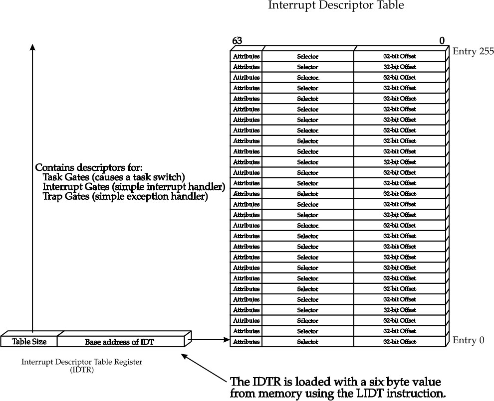
The IDT (Interrupt Descriptor Table) table not only contains the service routine descriptors but also some flags and protection levels.
Each entry in the IDT is called a gate, and each gate has the following structure:
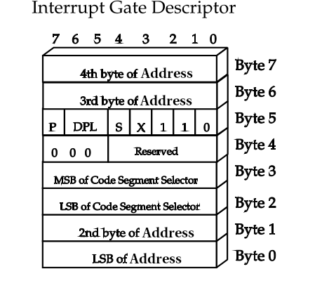
To locate the ISR (Interrupt Service Routine), we need the GDT (Global Descriptor Table) descriptor that references the code segment and the address where the ISR is located in ASM. As we can see in the image above, the bits that make up the address are not consecutive, so we need to read and combine their parts.
The fields of an IDT entry are as follows:
- Address: Memory address where the ISR is located
- Segment Selector: Descriptor of the code segment in the GDT
- Flags: Information about the type of interrupt, CPU architecture, and privileges
The flags are detailed below:
- Type: Indicates the type, the possible options are
0b101 task gate
0b110 interrupt gate
0b111 trap gate
- X: Indicates whether it is a 16/32-bit system
0: 16 bits
1: 32 bits
- S: Descriptor type. 1 for code or data segments, 0 for traps/interrupts/tasks
- DPL: Privilege, 2 bits. Contains the ring level, 0-kernel 3-userspace
- P: Indicates whether it is a valid interrupt
In our case, the final value of the FLAGS will be 0x8E:
P=1, DPL=00b, S=0, X=1, type=110b => 1000_1110b=10001110=0x8E
To indicate to the microprocessor where our IDT is located, we will use the idtr register:
We declare the functions related to the IDT and the GDT descriptor for the code segment GDT_CS. Remember that it is the second segment, and each segment occupies 8 bytes starting from 0.
#ifndef IDT_H
#define IDT_H

/* GDT Code Segment selector */
#define GDT_CS 0x08

/* Functions implemented in idt.c */
void set_idt_gate(int n, unsigned int isr_address);
void set_idt();

#endif
In the following file, we define two functions: set_idt_gate, which fills the IDT table with the interrupt IDs and the memory positions of the ISRs in ASM, and set_idt, which loads the IDT descriptor into the idtr register. We will also define some structures, such as idt_gate, which contains the information of an IDT entry, and idt_register, which is the descriptor that contains the base of the IDT and its size.
idt is an array of 256 positions of idt_gate structures, and idt_reg is the idt_register type descriptor.
#include "idt.h"

/* How every interrupt gate is defined */
typedef struct {
    unsigned short low_address; /* Lower 16 bits of handler function address */
    unsigned short sel; /* GDT Code segment selector */
    unsigned char always0;
    unsigned char flags;
    unsigned short high_address; /* Higher 16 bits of handler function address */
} __attribute__((packed)) idt_gate;

/* A pointer to the array of interrupt handlers.
 * Assembly instruction 'lidt' will read it */
typedef struct {
    unsigned short limit;
    unsigned int base;
} __attribute__((packed)) idt_register;


#define IDT_ENTRIES 256

idt_gate idt[IDT_ENTRIES];// Array of gates
idt_register idt_reg;


void set_idt_gate(int n, unsigned int isr_address) {
    idt[n].low_address = (isr_address & 0xFFFF);
    idt[n].sel = GDT_CS;
    idt[n].always0 = 0;
    idt[n].flags = 0x8E;
    idt[n].high_address = (isr_address >> 16) & 0xFFFF;
}

void set_idt() {
    idt_reg.base = (unsigned int) &idt;
    idt_reg.limit = IDT_ENTRIES * sizeof(idt_gate) - 1;
    /* Don't make the mistake of loading &idt -- always load &idt_reg */
    __asm__ __volatile__("lidtl (%0)" : : "r" (&idt_reg));
}
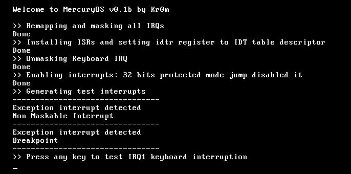
Finally, we remap the IRQs and install the ISRs from the main function of the kernel. We generate some interrupt codes and wait for a key to be pressed on the keyboard. If this happens, we read the key to clear the keyboard buffer and continue generating interrupts by pressing keys. We still don’t read the key code.
#include "../drivers/screen.h"
#include "util.h"

#include "irqs.h"
#include "isrs.h"

void main() {
    clear_screen();
    print_string("Welcome to MercuryOS v0.1b by Kr0m\n", 0, 0);
    print_string("\n", -1, -1);

    print_string(">> Remapping and masking all IRQs\n", -1, -1);
    remap_irqs();
    print_string("Done\n", -1, -1);

    print_string(">> Installing ISRs and setting idtr register to IDT table descriptor\n", -1, -1);
    isr_install();
    print_string("Done\n", -1, -1);

    print_string(">> Unmasking Keyboard IRQ\n", -1, -1);
    unmask_irq(1);
    print_string("Done\n", -1, -1);

    print_string(">> Enabling interrupts: 32 bits protected mode jump disabled it\n", -1, -1);
    enable_interrupts();
    print_string("Done\n", -1, -1);

    print_string(">> Generating test interrupts\n", -1, -1);
    /* Test the interrupts */
    print_string("--------------------------------\n", -1, -1);
    __asm__ __volatile__("int $2");
    __asm__ __volatile__("int $3");
    //__asm__ __volatile__("int $33");

    print_string(">> Press any key to test IRQ1 keyboard interruption\n", -1, -1);
}
Since the kernel has grown, we need to increase the size of the sectors to be loaded in the bootloader:
KERNEL_SIZE equ 19
We need to add kernel/interrupts.o to our Makefile.
OBJ = ${C_SOURCES:.c=.o kernel/interrupts.o}
Compile the kernel and load it into Qemu:
All changes to existing files have been explained in detail, but I still provide a tar.gz of the entire project code.
If we are unsure whether we are using PICs or any other set of chips to handle interrupts, we can run Qemu with the -M help option:
Supported machines are:
pc                   Standard PC (i440FX + PIIX, 1996) (alias of pc-i440fx-4.1)
pc-i440fx-4.1        Standard PC (i440FX + PIIX, 1996) (default)
pc-i440fx-4.0        Standard PC (i440FX + PIIX, 1996)
pc-i440fx-3.1        Standard PC (i440FX + PIIX, 1996)
pc-i440fx-3.0        Standard PC (i440FX + PIIX, 1996)
pc-i440fx-2.9        Standard PC (i440FX + PIIX, 1996)
pc-i440fx-2.8        Standard PC (i440FX + PIIX, 1996)
pc-i440fx-2.7        Standard PC (i440FX + PIIX, 1996)
pc-i440fx-2.6        Standard PC (i440FX + PIIX, 1996)
pc-i440fx-2.5        Standard PC (i440FX + PIIX, 1996)
pc-i440fx-2.4        Standard PC (i440FX + PIIX, 1996)
pc-i440fx-2.3        Standard PC (i440FX + PIIX, 1996)
pc-i440fx-2.2        Standard PC (i440FX + PIIX, 1996)
pc-i440fx-2.12       Standard PC (i440FX + PIIX, 1996)
pc-i440fx-2.11       Standard PC (i440FX + PIIX, 1996)
pc-i440fx-2.10       Standard PC (i440FX + PIIX, 1996)
pc-i440fx-2.1        Standard PC (i440FX + PIIX, 1996)
pc-i440fx-2.0        Standard PC (i440FX + PIIX, 1996)
pc-i440fx-1.7        Standard PC (i440FX + PIIX, 1996)
pc-i440fx-1.6        Standard PC (i440FX + PIIX, 1996)
pc-i440fx-1.5        Standard PC (i440FX + PIIX, 1996)
pc-i440fx-1.4        Standard PC (i440FX + PIIX, 1996)
pc-1.3               Standard PC (i440FX + PIIX, 1996)
pc-1.2               Standard PC (i440FX + PIIX, 1996)
pc-1.1               Standard PC (i440FX + PIIX, 1996)
pc-1.0               Standard PC (i440FX + PIIX, 1996)
pc-0.15              Standard PC (i440FX + PIIX, 1996) (deprecated)
pc-0.14              Standard PC (i440FX + PIIX, 1996) (deprecated)
pc-0.13              Standard PC (i440FX + PIIX, 1996) (deprecated)
pc-0.12              Standard PC (i440FX + PIIX, 1996) (deprecated)
q35                  Standard PC (Q35 + ICH9, 2009) (alias of pc-q35-4.1)
pc-q35-4.1           Standard PC (Q35 + ICH9, 2009)
pc-q35-4.0.1         Standard PC (Q35 + ICH9, 2009)
pc-q35-4.0           Standard PC (Q35 + ICH9, 2009)
pc-q35-3.1           Standard PC (Q35 + ICH9, 2009)
pc-q35-3.0           Standard PC (Q35 + ICH9, 2009)
pc-q35-2.9           Standard PC (Q35 + ICH9, 2009)
pc-q35-2.8           Standard PC (Q35 + ICH9, 2009)
pc-q35-2.7           Standard PC (Q35 + ICH9, 2009)
pc-q35-2.6           Standard PC (Q35 + ICH9, 2009)
pc-q35-2.5           Standard PC (Q35 + ICH9, 2009)
pc-q35-2.4           Standard PC (Q35 + ICH9, 2009)
pc-q35-2.12          Standard PC (Q35 + ICH9, 2009)
pc-q35-2.11          Standard PC (Q35 + ICH9, 2009)
pc-q35-2.10          Standard PC (Q35 + ICH9, 2009)
isapc                ISA-only PC
none                 empty machine
As we can see, it uses PIIX by default.