To take full advantage of the CPU, we must switch to 32-bit protected mode. The extra features that this mode offers us are: 32-bit registers, two additional general-purpose registers, fs/gs, the ability to access memory addresses up to 0xffffffff 4GB, a more advanced segmented memory system that will allow us to protect certain segments so that user applications do not have access to them, a virtual memory system to swap less-used data to disk, and a more sophisticated interrupt management system.
Before we begin, it is recommended that you read these previous articles:
The content presented in this article is very dense. If you don’t understand it at first, it’s normal. Read it as many times as you need, and gradually all the pieces will fit together.
To switch to this mode, we will have to prepare a GDT: global descriptor table , where we will define the memory segments and their attributes. This is necessary if we want to use high-level programming languages such as C.
In addition, once we switch to 32 bits, we will no longer be able to switch back to 16-bit mode, and we will not be able to make calls to BIOS interrupts since they were designed to work in 16-bit mode. If we try, the system will crash.
NOTE: A 32-bit OS is capable of switching back to 16-bit mode, but this causes more problems than it solves, especially in terms of performance.
Something very important to note is that when using GDT, we will no longer refer to memory positions by indicating the segment:offset, but we will have a table with segment descriptors in RAM. By accessing the segment descriptor, we will obtain the base address of the segment we want to access.
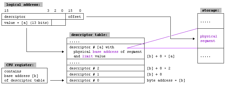
Each segment descriptor has the following information:
- Base address (32 bits): Defines where the segment starts.
- Segment limit (20 bits): Defines the size of the segment.
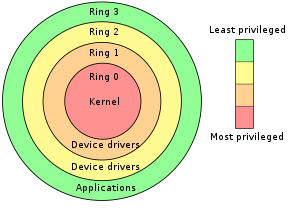
- Various flags: Privilege level (ring), whether the segment is RW/RO…
The flag bits have the following meanings: **P:** Present bit. Must be 1 for all valid selectors.
DPL: Privilege, 2 bits. Contains the ring level, 0-kernel 3-userspace.
S: Descriptor type. 1 for code or data segments, 0 for traps/interrupts/tasks.
Code: If set to 1, code execution is allowed in this segment. If it is 0, it is a data segment.
Conforming:
If it is a data segment, this bit indicates the direction in which the data will grow. If it is 0, it will grow towards lower memory addresses, otherwise towards higher ones.
If it is a code segment, a value of 0 indicates that the code in this segment cannot be executed from a lower privilege level. This way, we can protect the segments that the kernel will use from the userland.
R/W:
If it is a data segment, this bit indicates whether it can be written to. Reading is always allowed in a data segment.
If it is a code segment, this bit indicates whether it can be read from. Writing is never allowed in a code segment.
Accessed: Frequently used for debugging, when the CPU accesses this segment, it sets it to 1.
Gr: Granularity bit. Indicates the granularity of the segments. If it is set to 0, the segment limits are expressed in units of 1B, if it is set to 1, they are expressed in units of 4KB.
D/B: If set to 1, it indicates that the segment will contain 32-bit data, otherwise 16-bit.
L: Not used in 32-bit mode.
AVL: This bit can be used for our own purposes, such as debugging, but we will not use it.
A segment descriptor has the following appearance:
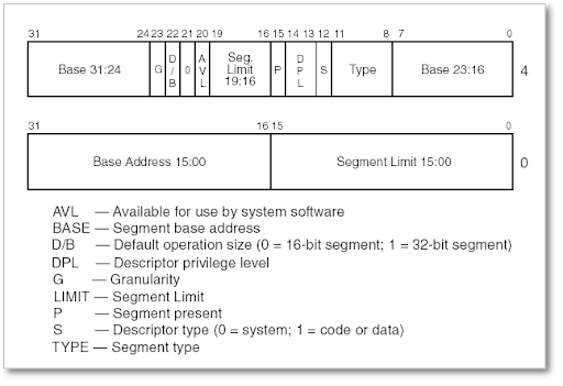
As we can see, the order of the data is completely illogical. The base address is fragmented into three parts, which must be joined to form the total address:
16-31: 16bits
0-7: 8bits
24-31: 8bits
In total, 32 bits: 16+8+8=32 bits.
As I said, it’s an absolute madness. I suppose it must be due to some hardware restriction or to take advantage of some hardware feature to perform some operation on this data or some explanation that escapes my understanding. As we can see in the image, the same thing happens with the segment limit.
We are going to adopt the system explained in Intel’s Developer Manual: basic flat model. This consists of two memory segments, one for data and one for code, but whose addresses overlap. This way everything will be simpler, there will be no protection between segments, no paging, no virtual memory. Both segments will be of the maximum addressable size with 32 bits: 2^32=4294967296 bits -> 4GB and can be used for both data and code since we are going to configure the start and end addresses to overlap.
In addition to the data and code entries, the CPU requires that the first entry in the segment descriptor table be invalid, an 8-byte structure of zeros.
This invalid entry is a mechanism for error detection in case we forget to set the segment register before accessing the memory address. If we do not set the segment, it will be set to 0, the GDT segment descriptor 0 with incorrect data will be used, and the CPU will jump with an exception error.
In assembly language, we simply need to define variables of the appropriate size with the correct values according to the type (code/data) of the segment we are defining.
; null GDT descriptor
gdt_start:
    dd 0x0 ; 4 byte
    dd 0x0 ; 4 byte

; GDT for code segment.
gdt_code:
    dw 0xffff    ; segment limit, bits 0-15
    dw 0x0       ; segment base, bits 0-15
    db 0x0       ; segment base, bits 16-23
    db 10011010b ; flags (8 bits)
    db 11001111b ; flags (4 bits) + segment limit, bits 16-19
    db 0x0       ; segment base, bits 24-31

; GDT for data segment. base and length identical to code segment(overlap)
gdt_data:
    dw 0xffff
    dw 0x0
    db 0x0
    db 10010010b
    db 11001111b
    db 0x0

gdt_end:

; GDT descriptor
gdt_descriptor:
    dw gdt_end - gdt_start - 1 ; gdt size (16 bit), always one less of its true size
    dd gdt_start ; gdt start address (32 bit)

; define some constants for later use
CODE_SEG equ gdt_code - gdt_start ; segment descriptor of code segment
DATA_SEG equ gdt_data - gdt_start ; segment descriptor of data segment
Let’s analyze the flags of the code segment:
db 10011010b ; flags (8 bits)
P: 1
DPL: 00
S: 1
Type(4bits):
    Code: 1
    Conforming: 0
    R/W: 1
    Accessed: 0
db 11001111b ; flags (4 bits) + segment limit, bits 16-19
G: 1
D/B: 1
L: 0
AVL: 0
The data segment is very similar:
db 10010010b
P: 1
DPL: 00
S: 1
Type(4bits):
    Code: 0
    Conforming: 0
    R/W: 1
    Accessed: 0
NOTE: Code: 0. We do not allow code execution since it is a data segment.
db 11001111b
G: 1
D/B: 1
L: 0
AVL: 0
We calculate the size and starting address of the GDT table to form the table descriptor. This data will be necessary for the CPU to load the GDT using the lgdt instruction.
; GDT descriptor
gdt_descriptor:
    dw gdt_end - gdt_start - 1 ; gdt size (16 bit), always one less of its true size
    dd gdt_start ; gdt start address (32 bit)
Thanks to the GDT table descriptor, the CPU will know the memory address where the table starts. Due to this, all references to a GDT table segment descriptor are indicated from the starting address of the table. For this reason, to generate the constants (equ) with the memory address of the code and data segment descriptor, we will have to subtract the address where the GDT starts.
CODE_SEG equ gdt_code - gdt_start
DATA_SEG equ gdt_data - gdt_start
Until now, to print a text on the screen, we simply assigned the correct value to the al register and called the 0x10 interrupt. But in 32-bit mode, all of this changes. First of all, the screen can have different resolutions and two modes: text mode and graphics mode. What is displayed on the screen is a visual representation of what is in a certain memory position. Therefore, to manipulate the output on the screen, we must manipulate a specific memory range. Devices that work in this way, such as graphics cards, are called memory-mapped hardware .
When a computer boots up, it does so in a very simple video mode VGA: Video Graphics Array in color text mode with character dimensions of 80x25. In text mode, the programmer does not need to render individual pixels to describe a character, the font has already been defined in the internal memory of the graphics card. Each character on the screen is represented by two bytes in memory, the first byte is the ASCII code associated with the character and the second is the character attributes, such as color, background color, and whether it should blink.
Therefore, if we want to display a character on the screen, we must set an ASCII code and its attributes at the correct memory position, which is usually 0xb8000. It should be noted that although the screen has rows and columns as coordinates, the video memory is sequential, and the formula for calculating the memory address associated with each coordinate is:
memoryPosition = 0xb8000 + 2 * (row * 80 + col)
Our basic screen writing code will basically execute these steps:
- Le pasamos la localización en memoria del string a imprimir a la función mediante el registros ebx
| -> Copiamos en al el contenido de ebx, carácter a imprimir
| - Seteamos ah a 0x0f, text blanco sobre fondo negro
| |- Comprobamos final de string
| |- Movemos ax a la posición de memoria de video
| |- Adelantamos en una byte la dirección de memoria desde donde estamos leyendo: add ebx, 1
| |- Adelantamos en dos bytes(char+attr) la dirección de memoria donde estamos escribiendo: add edx, 2
--|Loop
 -> Fin
Let’s see it in assembly code:
[bits 32] ; using 32-bit protected mode

; constant definitions
VIDEO_MEMORY equ 0xb8000 ; memory address
;WHITE_ON_BLACK equ 0x0f ; the color byte for each character
WHITE_ON_BLACK equ 0x40 ; the color byte for each character

print_string_pm:
    pusha
    mov edx, VIDEO_MEMORY; edx now has video memory address

print_string_pm_loop:
    mov al, [ebx] ; memory address of char to print
    mov ah, WHITE_ON_BLACK ; attr to print

    cmp al, 0 ; check if end of string
    je print_string_pm_done

    mov [edx], ax ; store character(al) + attribute(ah) in video memory, in that step we have printed the char to screen
    add ebx, 1 ; next char to read from ebx
    add edx, 2 ; next char to write in video memory position

    jmp print_string_pm_loop

print_string_pm_done:
    popa
    ret
The problem with this routine is that it always prints the string in the upper left of the screen and will overwrite previous messages without scrolling. This could be solved, but we won’t waste any more time on it since we will soon be loading code written in a high-level language that will make our task easier.
The last piece of the puzzle is to tell the CPU how to switch to 32-bit protected mode. To do this, we will disable interrupts since they are intended to be handled by the BIOS, which expects everything to work in 16-bit mode. We will load the GDT that we have prepared and set the cr0 register of the CPU through a general-purpose register. By doing this, all the code in our bootloader is moved to the memory positions indicated in the code segment descriptor, and the data to the memory positions indicated in the data segment descriptor.
In principle, we should already be operating in 32-bit protected mode, but the change can be dangerous due to the CPU’s pipelining . This means that the CPU can fetch upcoming operations while executing the current one, all in one clock cycle. This system is invalidated with operations such as jmp or call, since in jumps or calls, the destination is unknown, and it is impossible to preload future instructions. If there is a jump to another memory segment, the pipeline is discarded. We will use precisely this to force the CPU to discard all pending operations in its pipeline.
In 32-bit protected mode, when we indicate a SEGMENT:OFFSET address, the segment no longer indicates the value of the memory segment we want to access, but rather the segment descriptor of the GDT that contains the information of the segment we want to access.
To perform the far jump and discard the pipeline data, we will execute a jmp CODE_SEG:init_pm jump to:
The base address indicated by the code segment descriptor
With the offset where the init_pm label is located
When we switch to 32-bit protected mode, the cs register must be set to the code segment descriptor of the GDT table, and the rest of the data registers to the data segment descriptor. When executing the jmp CODE_SEG:init_pm jump instruction, the cs register will be updated automatically, but we will have to set the data registers ourselves. Finally, we redefine our stack.
[bits 16]
switch_to_pm:
    cli ; disable interrupts
    lgdt [gdt_descriptor] ; load the GDT descriptor
    mov eax, cr0
    or eax, 0x1 ; set 32-bit mode bit in cr0
    mov cr0, eax
    jmp CODE_SEG:init_pm ; far jump by using a different segment

[bits 32]
init_pm: ; we are now using 32-bit instructions
    mov ax, DATA_SEG ; update the data segment registers
    mov ds, ax
    mov ss, ax
    mov es, ax
    mov fs, ax
    mov gs, ax

    mov ebp, 0x90000 ; update the stack right at the top of the free space
    mov esp, ebp

    call BEGIN_PM ; Call a well-known label with useful code
The main program would be this:
[org 0x7c00] ; bootloader offset
mov bp, 0x9000 ; set the stack
mov sp, bp
mov bx, MSG_REAL_MODE
call print ; This will be written after the BIOS messages
call switch_to_pm
jmp $ ; this will actually never be executed
%include "./boot_sect_print.asm"
%include "./32bit-gdt.asm"
%include "./32bit-print.asm"
%include "./32bit-switch.asm"
[bits 32]
BEGIN_PM: ; after the switch we will get here
mov ebx, MSG_PROT_MODE
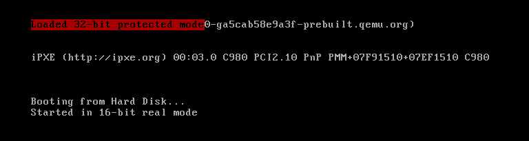
call print_string_pm ; Note that this will be written at the top left corner
jmp $
MSG_REAL_MODE db "Started in 16-bit real mode", 0
MSG_PROT_MODE db "Loaded 32-bit protected mode", 0
; bootsector
times 510-($-$$) db 0
dw 0xaa55
We generate the image:
We load it into Qemu: