If you are an electronics enthusiast, sooner or later, you will need to perform more advanced measurements than what a conventional multimeter allows. In such cases, an oscilloscope becomes very useful as it allows us to visualize signal types, duration, and voltage levels.
In this article, we will build our own homemade oscilloscope at a negligible cost (approx. €4.5) using a RaspberryPiPico and some additional hardware.
The required components are:
- RaspberryPi Pico
- Multimeter cables
- Multimeter crocodile clip cables
- Male banana connector
- Female banana connector
- Mini-USB cable
- OTG adapter
- Resistors : 75/470/100k ohm
- Plastic enclosure
- Android phone with version >= 6
The technical specifications of our scilloscope are:
Voltage: 24V
Max. Sampling Rate: 500kS/s (shared between channels)
Max. Analog bandwidth: 150kHz
Time/Div: 5us - 20secs
Memory depth depends on sampling rate. It ranges between 2kpts (shared between channels) and 20kpts in Run mode and up to 100kpts for Single shot captures.
Auto and Normal triggering
Cursors
X-Y Mode
FFT
Regarding the firmware, we will use Scoppy:
https://github.com/fhdm-dev/scoppy
You can download the firmware image for RaspberryPiPico from the following link:
https://github.com/fhdm-dev/scpdl1/raw/master/a/v15/scoppy-pico-v15.uf2
The process of loading the firmware is quite simple, you just need to follow these steps:
- Connect the
USBcable to yourPC. - Press the
BOOTSELbutton on theRaspberryPiPicoand while holding it, connect theMicro-USBcable. - It will be recognized as a storage unit: If using Windows, it will automatically mount the unit where you should copy the
scoppy-pico-v15.uf2file, then eject the unit.
usb_msc_auto_quirk: UQ_MSC_NO_GETMAXLUN set for USB mass storage device Raspberry Pi RP2 Boot (0x2e8a:0x0003)
ugen0.5: <Raspberry Pi RP2 Boot> at usbus0
umass0 on uhub0
umass0: <Raspberry Pi RP2 Boot, class 0/0, rev 1.10/1.00, addr 6> on usbus0
umass0:  SCSI over Bulk-Only; quirks = 0x0100
umass0:9:0: Attached to scbus9
da0 at umass-sim0 bus 0 scbus9 target 0 lun 0
da0: <RPI RP2 3> Removable Direct Access SCSI-2 device
da0: Serial Number E0C9125B0D9B
da0: 1.000MB/s transfers
da0: 128MB (262144 512 byte sectors)
da0: quirks=0x2<NO_6_BYTE>
You can check the device:
<RPI RP2 3> at scbus9 target 0 lun 0 (da0,pass6)
-
Mount the unit:
mount -t msdos /dev/da0s1 /mnt/aux -
Copy the firmware
cp /home/kr0m/scoppy-pico-v15.uf2 /mnt/aux/ -
Unmount
umount /mnt/aux
The electronic diagram is as follows:
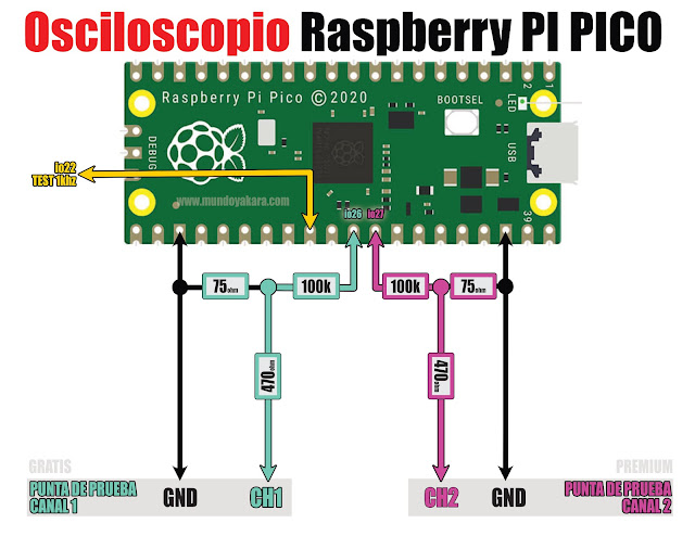
Note that the RaspberryPiPico allows for measuring two channels simultaneously, but the
Scoppy
software only allows us to use one channel for free. If you want to use both channels, you need to pay for the app. So, I will be content with one channel and only solder the CH1 part on the left side in blue on the diagram.
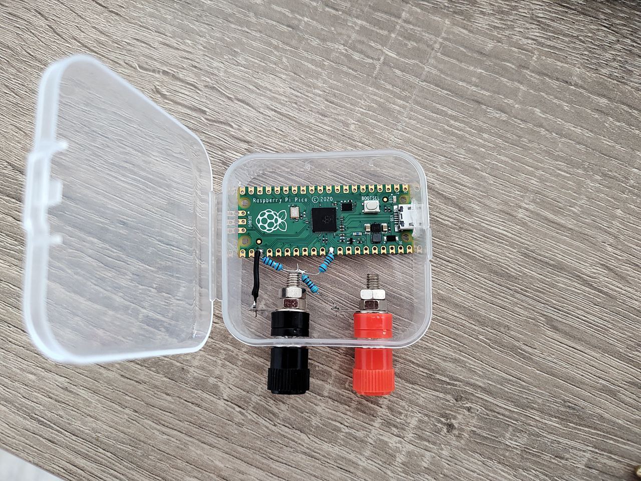
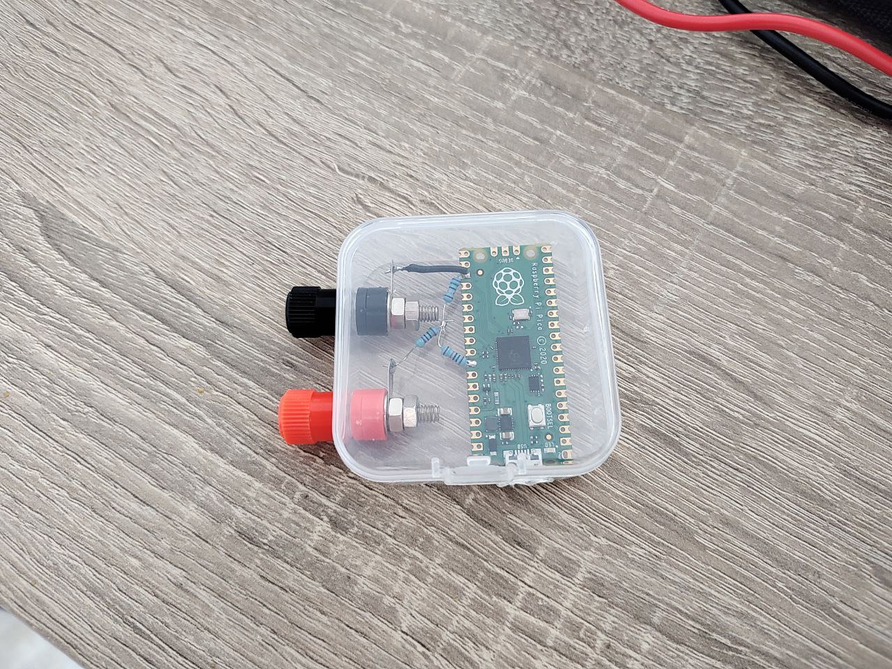
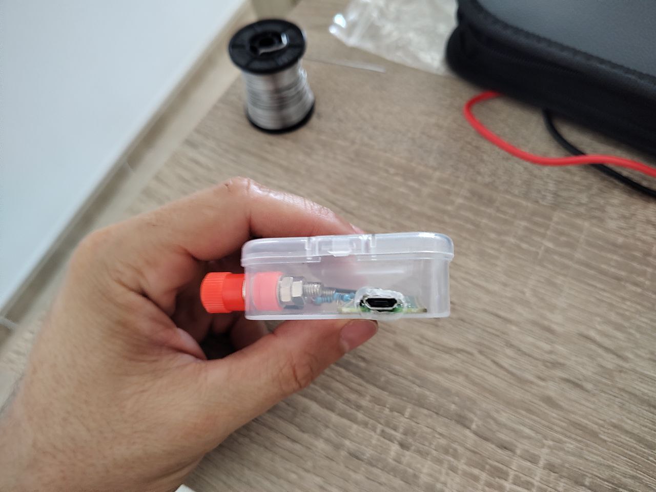
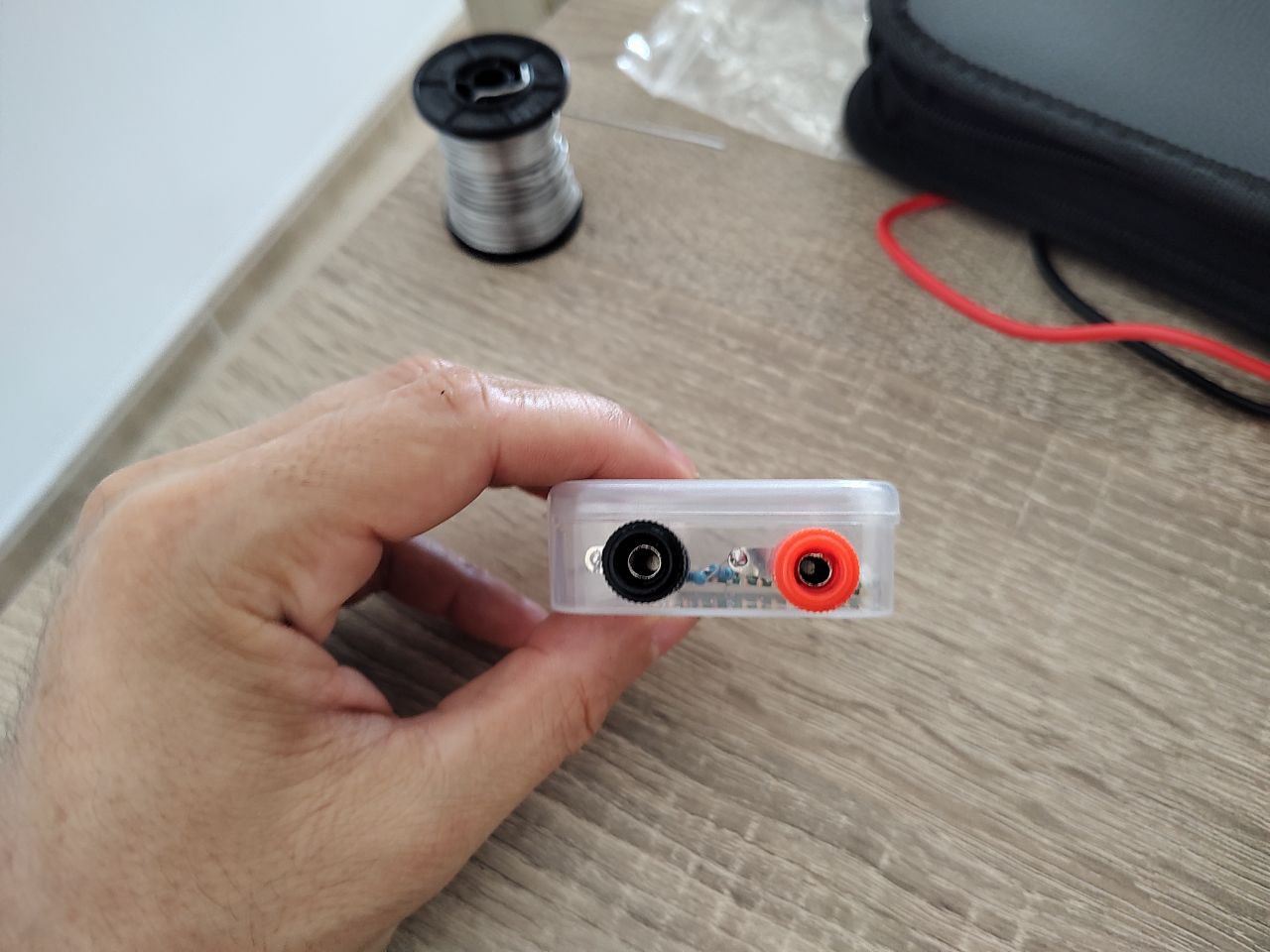
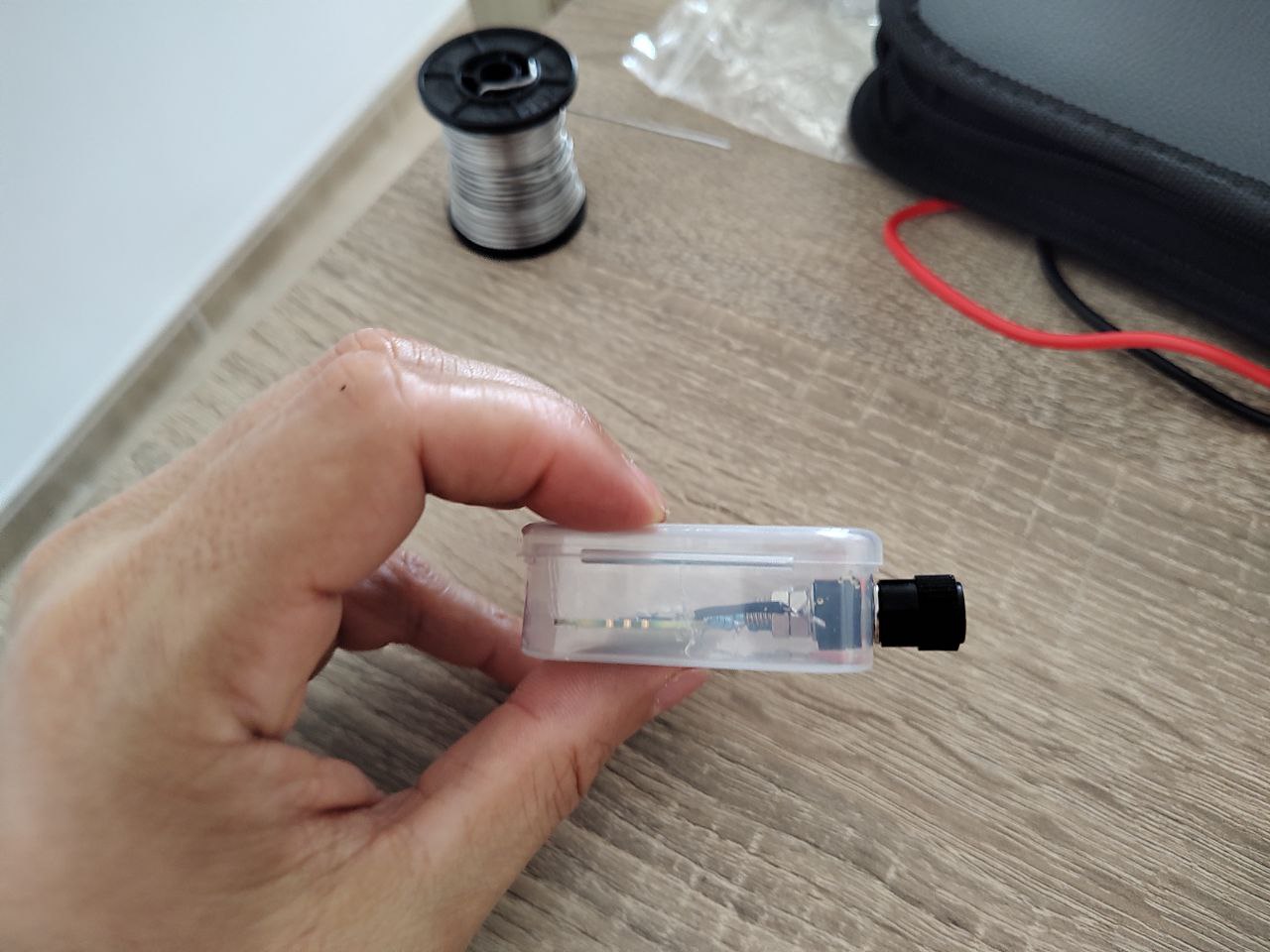
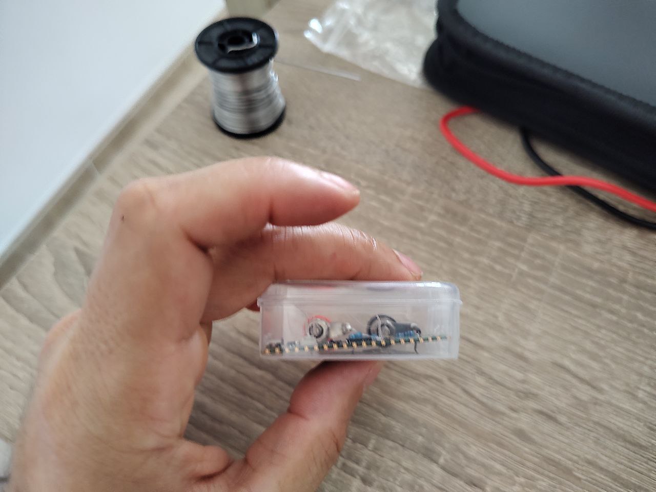
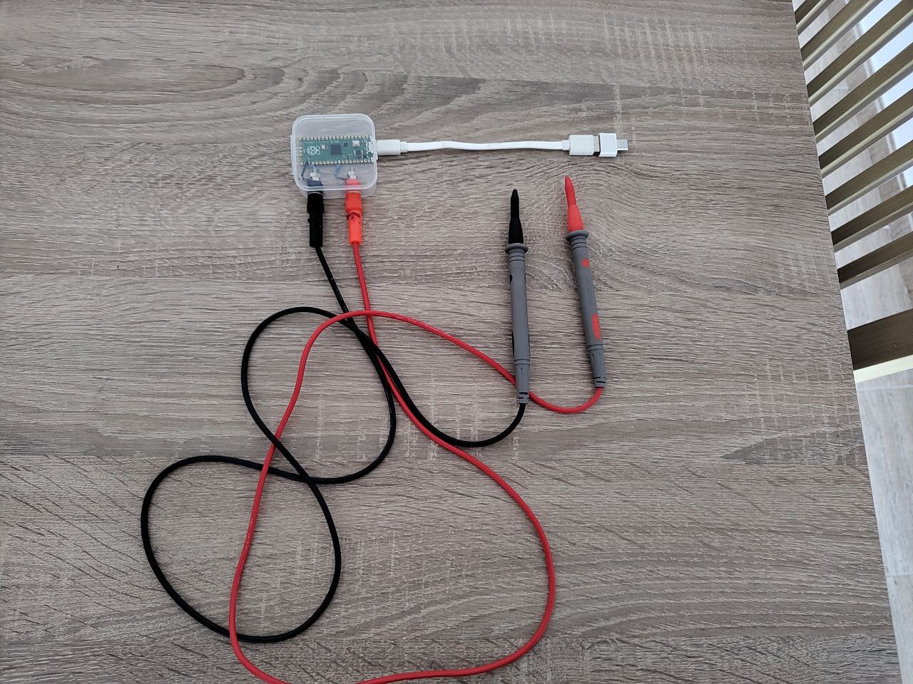
Once everything is assembled, it will look like this:
|
|
|
|
|
|
|
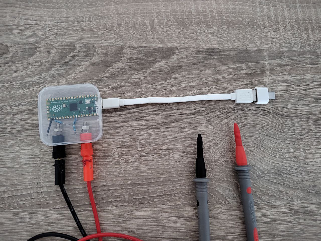
|
Regarding the sampling cables, as they come from Aliexpress, they have connectors for a multimeter. I had to cut the cable and solder them to the banana connectors.
The mobile phone will act as a data display screen. To achieve this, we need to install the Scoppy app.
Once installed, we check that the USB connection is OK:
USB: OK
Additionally, we need to configure the voltage range:
CH1 -> Configure voltage range(s)...
Min. Voltage: 0
Max. Voltage: 24
USB -> Connected device -> Firmware settings -> Channels -> Channel 1
Min. Voltage: 0
Max. Voltage: 24
Restart the RaspberryPiPico by disconnecting and reconnecting the USB cable.
From this point on, there is nothing else to do. We can now perform measurements. The default Scoppy firmware generates a test signal on io22 to test the proper functioning.
You can watch the entire process in this video: